1982 – RCV-150 Remote Controlled Vehicle System by Arthur B. Billet, principal engineer, Hydro Products, Inc., a Tetra Tech Co., wholly owned by Honeywell.
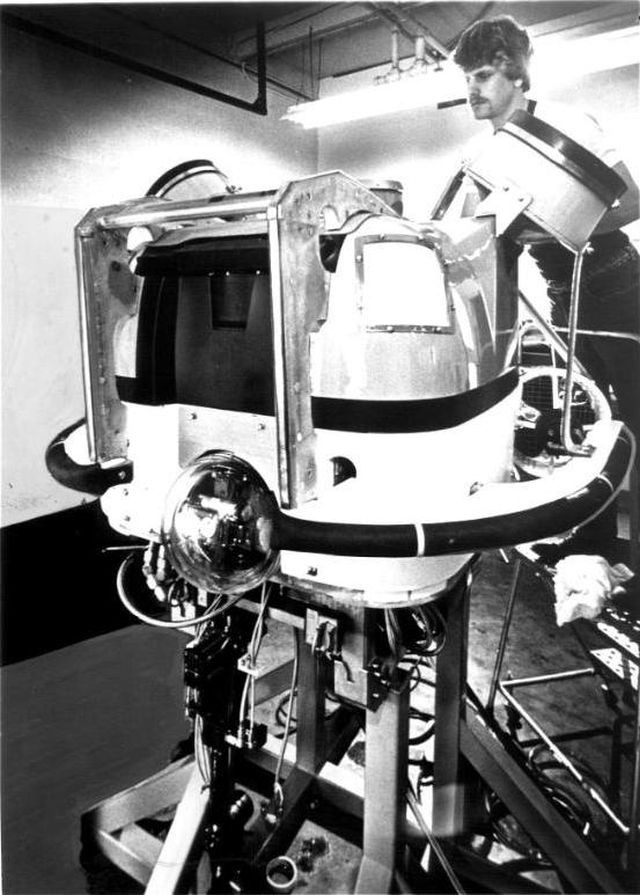
Technician checks out the RCV-150, Hydro Product's largest deep-diving robot vehicle, one of the increasing number of such remote-controlled devices that are rapidly replacing human divers for many underwater tasks. (MUST PHOTO CREDIT: Los Angeles Times Photo by Dave Gatley) Illustrates RCV, by Barbara Bry (Times), moved Monday, July 19. (c) 1982, Los Angeles Times.
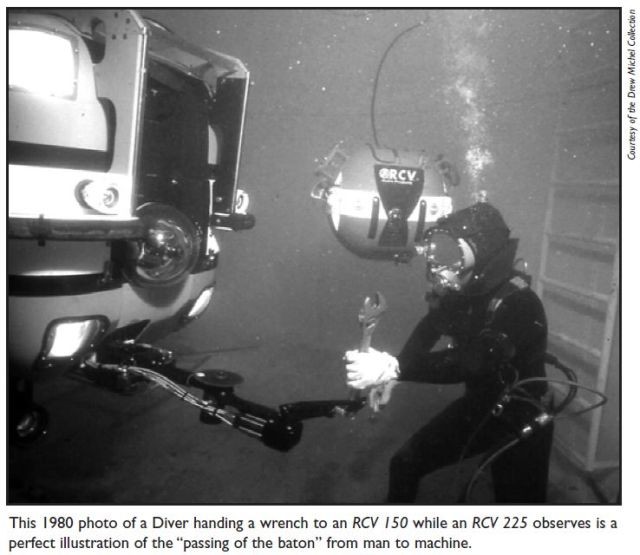
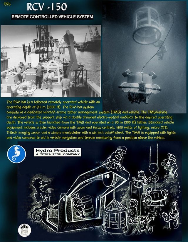
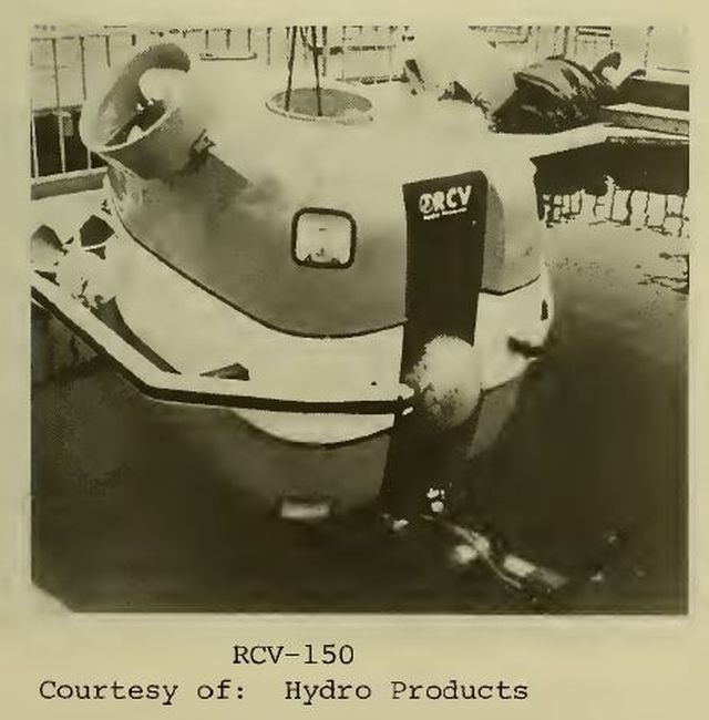
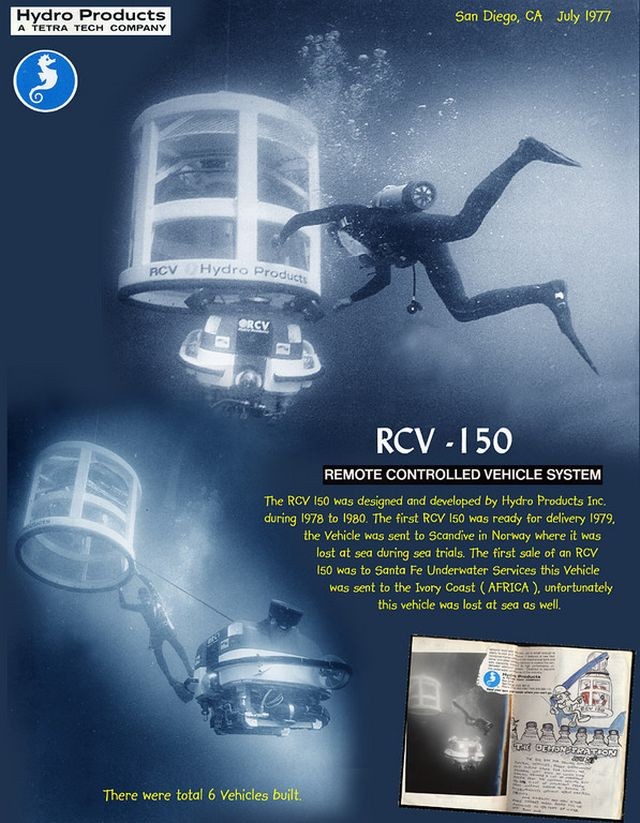
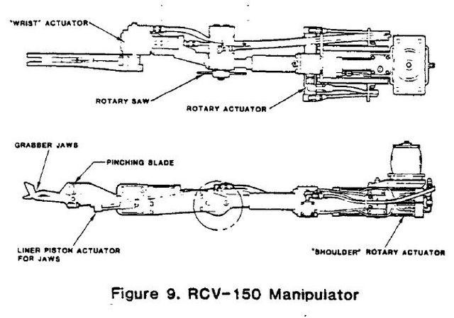
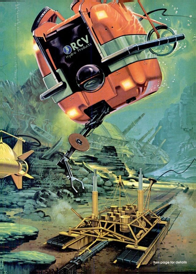
The big brother of the RCV -225, the RCV-150 was developed as a highly maneuverable, light-work capable ROV. This vehicle, in addition to being a flying eyeball, has a four function manipulator capability including both a rotary saw, pinching blade and grabber jaw. The RCV-150 has recently been fitted with a second four function arm extending the work capabilities to much more extensive and complex tasks.
MANIPULATOR ARM
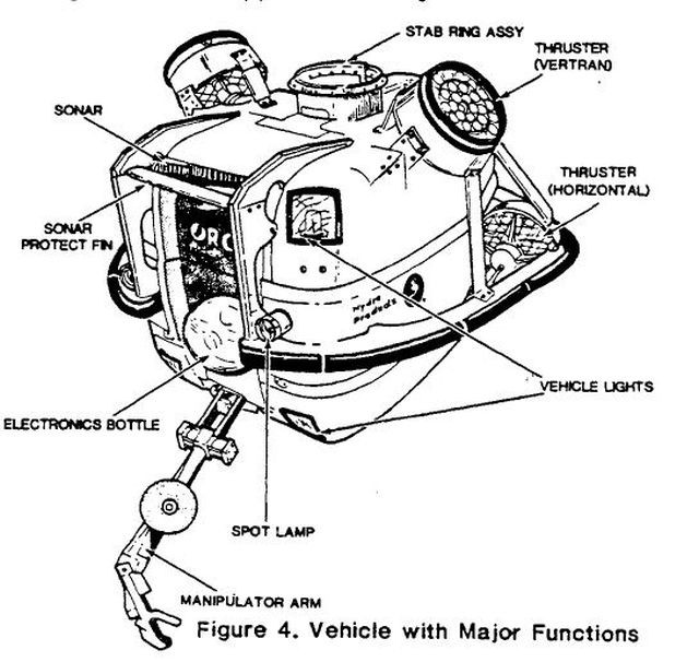
Figure 9 shows the manipulator assembly. The manipulator is a five-function work arm normally stowed inside the lower framework in the vehicle. A rotary actuator at a "shoulder" joint allows for stow and unstow motion of the arm. An actuator at the "wrist" allows grabber jaws to pivot in a 245-degree arc. The jaws are opened and closed by a linear piston actuator. A pinching blade, capable of cutting 3/4 inch polypropylene line, is actuated simultaneously with the jaws.
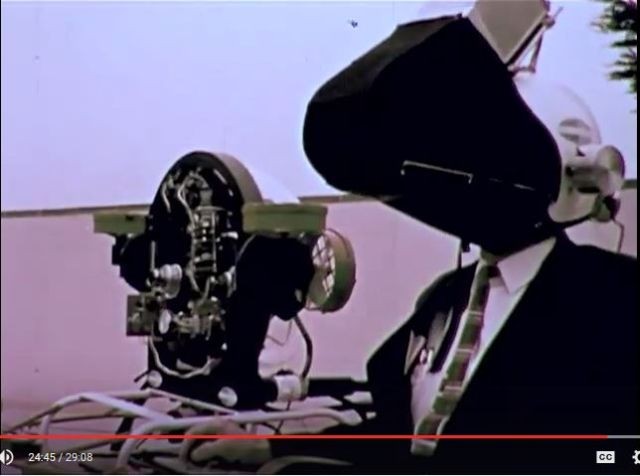
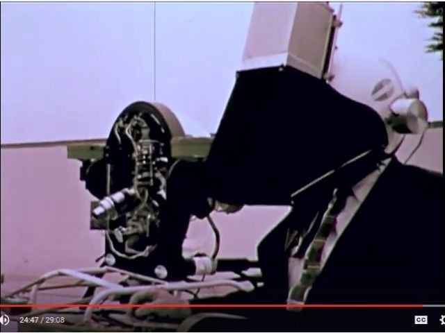
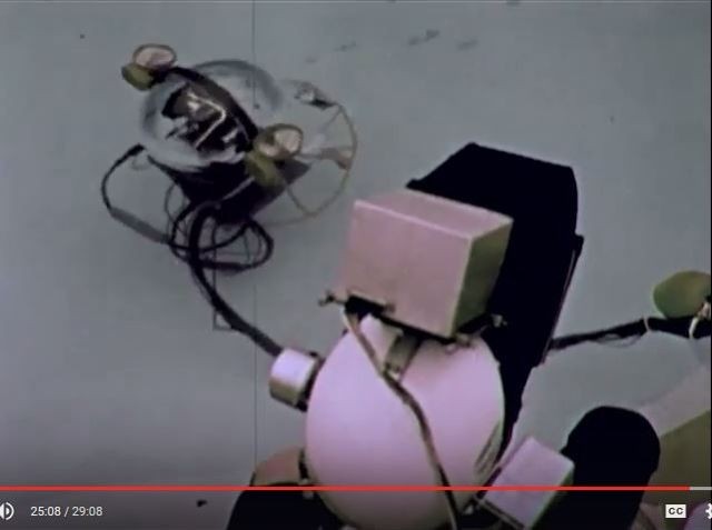
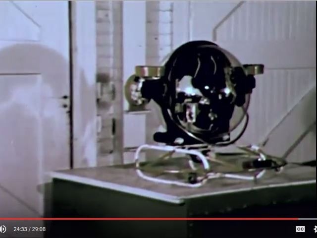
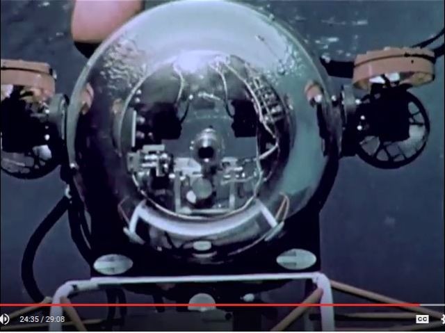
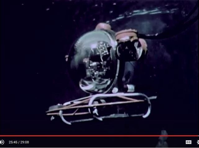
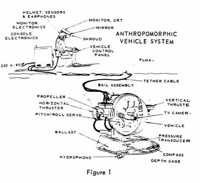
TV eye for underwater work A new device for underwater inspection work is Anthro, a remotely controlled submersible with a 20-inch-diameter plastic bubble for a hull. A television display and propulsion controls-on board ship or on dry land-are connected to the vehicle by an umbilical. Anthro's TV camera is electronically "slaved" to the operator's head. As he moves his head, the scene he views is moving in exact synchronization. Headphones provide binaural sound-transmitted from hydrophones aboard Anthro-as an additional aid in orienting the vehicle. (If Anthro bumps into anything, the bump is heard topside.) Movement of Anthro-forward, reverse, up and down-is by hand controls. Device was developed by Hydro Products, San Diego. Source: Popular Mechanics, Nov 1973.
See ANTHRO – 24:24 into the clip.
ANTHROPOMORPHIC VEHICLE SYSTEM (aka ANTHRO).
Various stills from the above video showing duplicated (anthropomorphic) head movement.
Project headed by Willis "Will" R. Forman (seen in video above with "Deep View" submersible).
ANTHRO
Source: Remotely Operated Vehicles, by R. Frank Busby Associates, Inc., August 1979.
From 1958 through 1974 the U.S. Navy constructed and funded development of eight more ROVs. Three of these were additions and replacements for the original CURV, the others were primarily testbed vehicles for advancement in technology, two such vehicles were TORTUGA (not shown) and ANTHRO built by Hydro Products, San Diego, California.
The design goal of TORTUGA was to produce a small (relative to CURV) maneuverable underwater video system designed for close examination of normally inaccessible underwater areas. Although its military application is not publicly reported, TORTUGA' s shape, size and mode of operation indicates a potential for deployment from a submarine. Several experimental versions of TORTUGA were built, the first units relied on water jets for propulsion, later vehicles used propellers to increase maneuvering and responsiveness.
The ANTHRO (anthromorphic) vehicle was a follow-on to TORTUGA which was also constructed by Hydro Products with U.S. Navy funding. ANTHRO was developed to investigate a concept wherein normal human perception would be preserved in the vehicle. The technique employed was referred to as "head coupled" video presentation and involved slaving the vehicle and/or camera orientation to the operator's head attitude. The video presentation was mounted on, and moved with, the operator's head. Consequently, the scene being viewed moved in exact synchronization with the operator's head movement, and his memory recorded the relative location of all objects in the field of view. Binaural audio inputs (obtained from a pair of hydrophones on the vehicle) were also continuously provided to investigate the feasibility of detecting and localizing underwater objects either by their own self-generated sound or by reflected sound generated from the vehicle.
The ANTHRO operator's control station included an instrumented swivel chair and a helmet containing a television display (a 5 inch TV screen), roll, pitch and azimuth sensors and dual headphones. Manned controls for vehicle maneuvering, depth functions and television camera remote focus were provided at the operator's right hand. Vehicle depth was controlled by servo-controlled vertical thrusters which automatically maintained a desired depth.
SCAT (Submersible Cable-Activated Teleoperator) was a U.S. Navy-built follow-on to ANTHRO and served as a test-bed demonstration vehicle for the purpose of evaluating head-coupled television and three-dimensional television display.
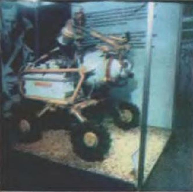
The Institute of Oceanology, USSR, capitalizing on experiences with the 4,000m CRAB-4000 in 1971, developed the MANTA vehicle. The operational theory behind MANTA was that it is practically impossible for a man to successfully operate a moving system without a proper feedback which acts upon the whole complex of sensors within his central nervous system (Mikhaltsev, 1973). A group of tenso-sensors was mounted on MANTA and a special servo-controlled, hydraulically-driven operator's chair which closed the feedback circuit, was constructed. The chair repeated all the roll and pitch movements of the underwater vehicle and allowed the operator to feel MANTA' s maneuvering. Further sophistication was added by incorporating the feedback provided by the manipulator's tenso-sensors into a simple computer which gave the preprogrammed computer the ability to command the manipulator system. As of 1973 the preprogramming was fulfilled, but only under laboratory conditions.
Anthropomorphic Vehicle System
by Robert L. Hittleman, Manager, Systems Division
Oceanographic Engineering Company, An affiliate of Dillingham Corporation, and
Will Forman, Submersible Project Manager at Naval Undersea Research & Development Center
Published in: Underwater Photo-Optical Instrumentation Applications III by Seibert Q. Duntley; Joe J. Lones; H. S. Weisbrod, Honolulu | January 01, 1971.
Abstract
The efficient performance of any task in the hostile underwater environment requires that due care be exercised in the design of the man-machine interface to take full advantage of the enormous potential available in the human mechanism. In particular, it was believed that significant benefits could be realized if the human brain was introduced as an integrally functioning element of an under-water remote controlled vehicle system.
Dillingham personnel, working in close coordination with Dr. McLean and Will Forman of the Naval Undersea Research and Development Center, San Diego, investigated a concept wherein normal human perception would be preserved in the design of a remote controlled, miniature, unmanned submersible. The technique involved coupling the vehicle operator's head motion and direction to that of the vehicle and its television camera. A pair of hydrophones on the vehicle provides a binaural listening capability. The objective was to demonstrate the feasibility of directing underwater systems using acoustic and visual sensors which acquire information in the same manner as does the "human mechanism"–thus giving rise to the Anthropomorphic identification; that is, a machine system designed with human characteristics In this system, the operator's brain functions as a neurological computer and is a functional element of the control and data processing system. Unnatural mental coordinate-transformation type operations inherent in previous man-machine interface designs would thus be eliminated.
System Design
The system was designed with the criteria of simplicity and low cost foremost; in order that this experimental, feasibility demonstration model be fabricated inexpensively and in the shortest time period possible. Maximum use of off-the-shelf equipment was made, and hard wiring, rather than printed circuit boards were used, in recognition of the one-of-a-kind nature of the development program. This latter feature also allowed one to incorporate design changes with relative ease.
The total system is shown in Figure 1, and consists of:
. a submersible vehicle and tether cable,
. an operator's control station, and
. an electronics console.
The vehicle has a 20" diameter, transparent plastic sphere.
Possibly related patent.
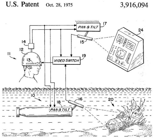
Submersible visual simulator for remotely piloted systems
Publication number US3916094 A
Publication type Grant
Publication date 28 Oct 1975
Filing date 21 Jun 1974
Inventors Frederick A Marrone
Original Assignee US Navy
ABSTRACT A visual simulator for obtaining the illusion of control presence in a remotely controlled vehicle comprises two television camera systems which are coupled to a cathode ray tube display carried by the head gear of the operator of the remote controlled vehicle. A video mixer or switch combines the images recorded by the two television camera systems into a single display. A position sensor attached to the helmet worn by the operator is connected to the video mixer to control the position of the scenes recorded by the two television camera systems on the cathode ray tube display.
SUMMARY OF THE INVENTION This invention overcomes the aforestated deficiencies of the prior art by providing a head controlled television monitoring system in which two television cameras are employed. The first camera is mounted on a remotely controlled vehicle to provide the customary exterior view from said vehicle. The second television camera is directed toward a control console for the vehicle. Of course, the control console may be at the operators position and the instruments and control positions thereon may be telemetered to the vehicle. The illusion of presence is further enhanced by combining the two views from the respective television cameras into a single cathode ray display. The two images are mixed in the cathode ray tube display in dependence upon a sensed position of the operators head. Thus, when the operator looks forward, he is presented a view of the exterior of the vehicle. However, when he moves his head in a predetermined direction to a predetermined position, the view afforded by the television camera monitoring console is presented on the viewing cathode ray display. In this fashion, an illusion of looking out a transparent. canopied cockpit on the front of the remote controlled vehicle is created with the control console placed adjacent said canopy.
STATEMENT OF THE OBJECTS OF INVENTION It is an object of this invention to provide an improved TV monitor system.
A further object of this invention is the provision of a TV monitoring system adapted for use in remote controlled vehicles.
A further object of this invention is the provision of a stereoscopic television system.
Another object of this invention is to provide a stereo-scopic television system for use in remotely controlled vehicles to enhance the control presence of said vehicles.
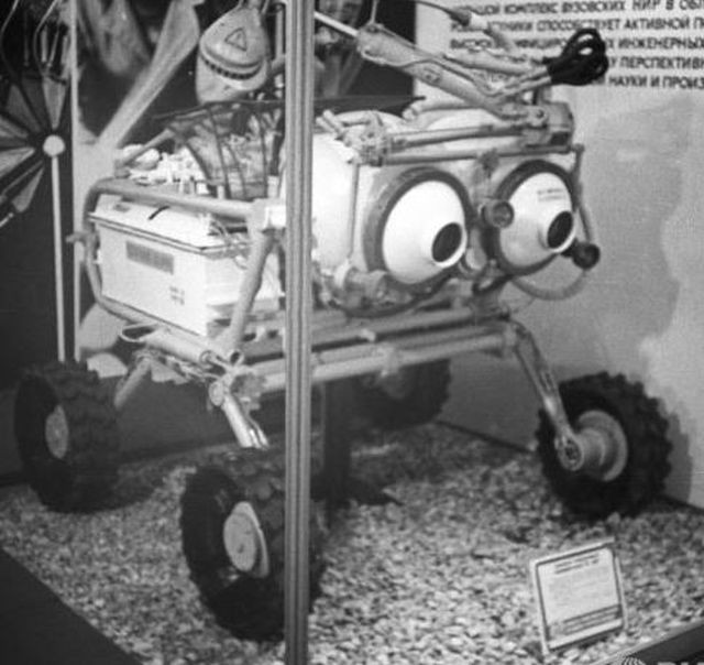
1966 – CRAB Remote-controlled Underwater Craft by Dr. Vyacheslav Yastrebov
"Aquator" [Дкватор] – a moving robot for underwater research – came out of the walls of the Bauman Institute. Designers believe that this device will become active assistant hydrologists, ocean scientists, biologists – all those who study the depths of the sea.
The CRAB is named "Aquator" in this article.
The Bauman Institute of Underwater Devices and Robotics is part of Moscow State Technical University, the oldest institute in Russia; it also is one of the largest. Before the Revolution it was called the "Imperial High School."
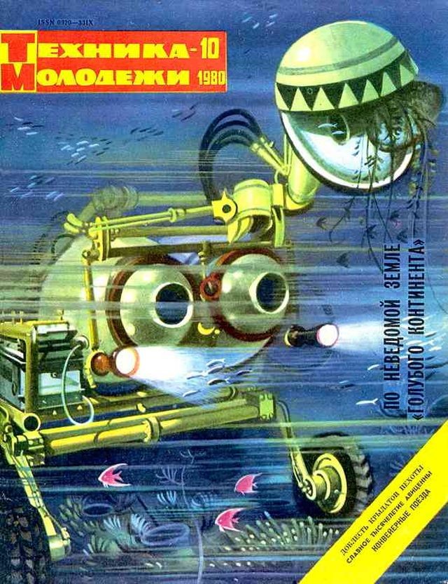
Source: Engineering – Youth 1980-10, page 10
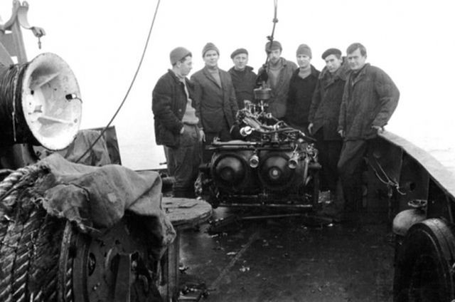
The "CRAB". Vyacheslav Yastrebov is on the far right in this photo.
The "Crab" was conceived as early at 1966 by Vyacheslav Yastrebov, Head of the Underwater Research Technique Laboratory. Yastrebov was one of the main designers of the robot. At the time, the most difficult problem was that of communication and a cable from the surface to the vehicle was the only feasible method. The use of computer-controlled programmes and master-slave manipulators was also envisioned, along with a television camera.
Two Crabs were built. The first was the "Crab 3,000" — a remote-controlled vehicle for depths of 3,000 m. The second crab, the "Crab 4,000" was said to be built in 1971, although the Crab 3,000 was undergoing sea trials in 1972!
Lunokhod gets into deep water
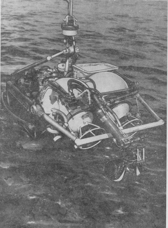
Soviet oceanologists have recently been testing a new device for exploring the ocean bed. Nicknamed the Crab, it is similar in conception to their mooncar—Lunokhod-1. The Crab is mobile, has apparatus for studying the sea floor and taking samples, and has a television system. The control crew work from a mother ship, which has a cable link with the Crab for transmitting commands, television pictures and any other signals.
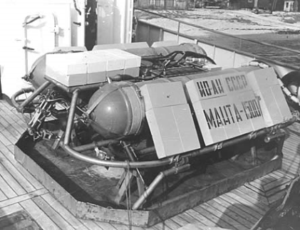
The Crab's first research mission was studying the underwater volcanoes in the Mediterranean, north of Sicily. The mother ship was the research vessel—the Akademik Sergei Vavilov—and the research team included designers of the Crab from the Academy of Sciences' Institute of Oceanology in Moscow. They used the Crab in two volcanic areas, lowering it at one time to a depth of 1250m. It sent back television pictures, took samples from the surface of the volcanoes, and, according to the head of the expedition, V. Yastrebov, generally worked successfully.
The 'crab' remote-controlled underwater craft by YASTREBOV, V. Text Source: Underwater Journal. 5:117-119:June 1973.
The 'Crab' remote-controlled underwater craft is intended to carry out simple operations for collecting sea-bed material and animal specimens from the ocean floor at depths of up to 3600 m. It carries a TV-system, a manipulator, a hydraulic power system, a remote-control system and an autonomous storage battery supply. The entire electronic section of the equipment is housed in the front part of the 'Crab' in spherical boxes which are provided with portholes through which observations are conducted with the aid of television and a photographic camera. The boxes carry a hinged telescopic manipulator, the gripping part of which is adjusted for picking up objects of any shape as well as loose ground samples. The manipulator has a range. relative to the immobile craft, 0.4 m. The whole craft is positioned on a three-bearing flat platform and may revolve, relative to the platform, around its vertical axis, for 320°, allowing scanning of the area when the craft is on the ocean floor. The spherical boxes with the manipulator may be inclined to 30° giving the craft the facility for scanning, and the manipulator the possibility of servicing, a circular zone with an inner diameter of 2.2 m and outer diameter of 3 m. The craft itself is 1.4 m long, 1 m. wide and 0.4 m high and weighs 620 kg in air. After scooping the sample. the manipulator turns back and stops in its extreme rear position over a bin into which the scooped materials are placed. (Author).
Source: Underwater Medicine and Related Sciences: A Guide to the Literature Volume 2 … By Margaret F. Werts, Charles 'N. Shilling
An Overview of Non-U.S. Underwater Remotely Manned Manipulators by A. B. Rechnitzer – Received 9 June 1975
U.S.S.R.
The U.S.S.R. is actively involved in automation research. The importance of this technology is evident by a special Commission on the Theory and Principles of Robot and Manipulation Devices within its Academy of Science. The Commission is responsible for forecasting development trends and the U.S.S.R. automation research program. The U.S.S.R. is putting significant emphasis on the development of robots and remotely operated systems involving supervisory control, artificial intelligence and systems development. Russian literature related to industrial robots and manipulators is extensive and reflects strong national interest and support active research, development and a high level of competence.
Research on undersea remotely manned systems at the Pyotr Shirshow Institute of Oceanology of the U.S.S.R. Academy of Sciences is comprehensive and reflects much innovation. Vyacheslav Yastrebov, Head of the Underwater Research Technique Laboratory leads the development of the theoretical and engineering principles contributing to the design of remote controlled underwater craft. Beginning in 1964 the aim of Yastrebov and his associates has been to develop systems for deep ocean research.
The first system to appear was called the Crab. The unmanned cable-controlled unit carried a TV system and photographer camera, a hinged telescopic manipulator, a hydraulic power system, a remote control system and an autonomous storage battery supply. The sample manipulator gripper could pick up objects of varying shapes at a maximum reach of 0.4 m.
The Crab can be landed on the sea floor to gain a stationary and stable condition. The undercarriage of the craft is fitted with a three-bearing platform that permits controlled rotation of the upper section containing the TV, camera and manipulator can be rotated around the vertical axis 320°. The upper section can also be inclined 30° for scanning and use of the manipulator through a concentric work area envelope with a 2.2 m inner dia. and 3 m outer dia. The manipulator scoop (gripper) is turned back (elbow) and retracted to position the sample over a storage bin. The manipulator and platform rotation are hydraulically powered.
Control commands and slow frame rate (10 frames per sec) television image are communicated to a surface support vessel via a coaxial cable. A frequency-time separation technique is used for transmitting control and TV-image signals at a carrier frequency of 3.5 Mc/s. Stepped finders are used in the craft as switching devices and information is transmitted via 22 channels.
The Crab went through its sea trials in the Black Sea in early 1972 down to a depth of 1500 m. Later the craft was used in the Tyrrhenian Sea to explore the tops of volcanic mountains summits at depths of 100-1200 m. Pictures of the sea-bed were obtained using TV and motion picture cameras in both the flying and resting modes. Specimens were collected using the manipulator.
An upgraded version of Crab Two has been built for operation to depths of 4000 m. Its manipulator, designed for 4000 m. use has 7° of freedom and is described as a copying manipulator (interpreted to mean master-slave). This manipulator has been tested aboard the U.S.S.R. manned submersible Sever-2.
MANTA
Experienced gained from the two versions of Crab has lead to the development of a system of operating near the sea floor. This craft, named Manta is equipped with thrusters and a push-button control panel. Manta encompasses many features common to the Crab. A key added feature is the surface controller's chair that is coupled to the Manta vehicle through a servo-feedback circuit that repeats the pitch and roll of the Manta to provide an operator sense of presence. This innovation has proven to be very effective when tested against the traditional fixed chair for the operator.
The Manta manipulator performance has been upgraded by the introduction of preprogrammed motion instructions to carry out repeat actions involved in grasping and storing collected samples.
Source: Mechanism and Machine Theory, 1977 Vol 12. pp. 51-56 Pergamon Press.
The Institute of Oceanology, USSR, capitalizing on experiences with the 4,000m CRAB-4000 in 1971, developed the MANTA vehicle. The operational theory behind MANTA was that it is practically impossible for a man to successfully operate a moving system without a proper feedback which acts upon the whole complex of sensors within his central nervous system (Mikhaltsev, 1973). A group of tenso-sensors was mounted on MANTA and a special servo-controlled, hydraulically-driven operator's chair which closed the feedback circuit, was constructed.
The chair repeated all the roll and pitch movements of the underwater vehicle and allowed the operator to feel MANTA' s maneuvering. Further sophistication was added by incorporating the feedback provided by the manipulator's tenso-sensors into a simple computer which gave the preprogrammed computer the ability to command the manipulator system. As of 1973 the preprogramming was fulfilled, but only under laboratory conditions. Source: Remotely operated vehicles / prepared by R. Frank Busby Associates, 1979.
CABLE CONTROLLED DEEP SUBMERGENCE TELEOPERATOR SYSTEM
Jean Vertut (CEA, Saclay, France) and Joel Charles (CERTSM, Toulon, France)
ABSTRACT
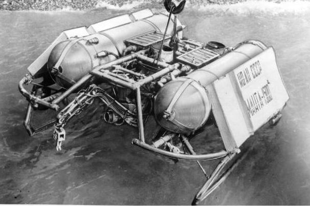
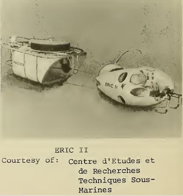
ERIC II, cable controlled deep submergence teleoperator system, is designed for remote observation, investigation and intervention from a surface ship, with a 6000 meters depth capability. The system is in development at CERTSM in Toulon Navy-Yard-France on contract of Ministere Des Armees; its main parts comprise first the heavy ancillary subsystems: cable handling gear, main cable, tether, PAGODE recovery fish, data and power transmission and second the ERIC II teleoperator fish and its control module. Special attention was paid at man-machine,interface problems in the early stage of development and the result is the current development of "telesymbiotic" oriented hardwares: head mobility with T.V. and microphones sensory feedback, force feedback dexterous arms on sponsorship of CEA-Saclay-France, agility concept in the fish dynamic control with inertia feedback by kinesthetic motorized sticks also with CEA cooperation. First significative real world experience on underwater dexterous manipulative tasks was gained in late 1974 with great success. First experimentation of ERIC II is scheduled for early 1977.
The teleoperator system is based on the MA-23 arms. See here.
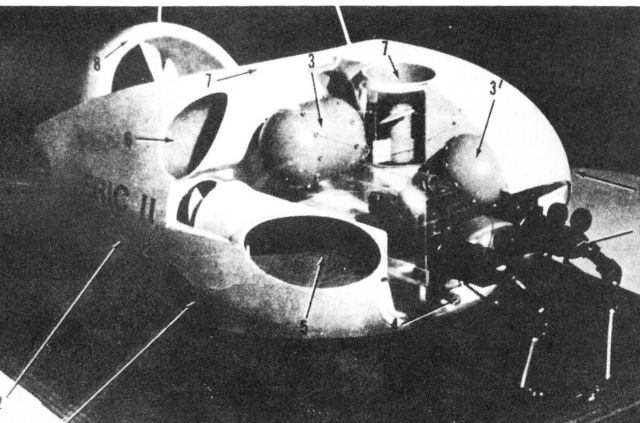
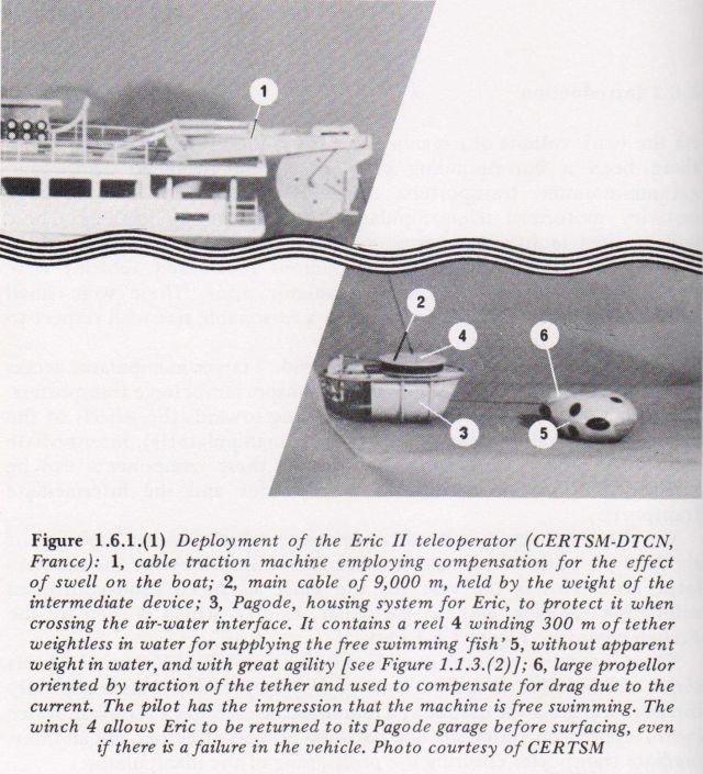
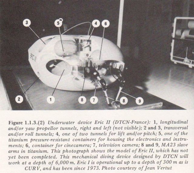
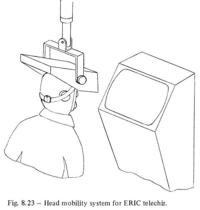
An unmanned manipulator submersible developed for the French Navy has been described in some detail by J. Charles and J. Vertut (Table controlled deep submergence teleoperator system', Mech. and Machine Theory, 1977, 12, p. 481). This is designed to search and investigate on the sea floor down to a depth of 6000 m. It consists of a 'fish-house' called PAGODE which acts as a lift between the bottom and the surface and carries the main cable and the 300 m tether cable for the neutral buoyancy teleoperator 'fish' which is called ERIC II (see Fig. 8.22 top picture above). The combined system is dropped to the required depth and then ERIC swims out of the 'fish house' to carry out the task. It is planned to have ultimately 6 degrees of freedom for the television camera, controlled by the rotation and movement of the operator's head in the support ship, the movements being in relation to his chair fixed in space. The telechir 'head' has binaural microphones connected to two earphones on the helmet in which the operator's head is placed (see Fig. 8.23). This helmet has binocular TV display and is counterweighted. ERIC weighs 4-5 tons and has 100 kW propulsive power supplied at 600 volts 400 Hz to keep the voltage control systems fairly constant and to transmit the required signals. The data transmission system is a composite one with analogue for specific purposes and digital for general purposes. The position of the 'fish' is determined over large areas by bottom acoustic transponders and panoramic sonar and locally by sonar and forward TV cameras. The basic intention is to mimic the overall capacity of a human diver without the limitations imposed by pressure. The system has a main propeller gimballed so that it always thrusts along the tiller tension direction with a tether so that it swims like a free body. It has three pairs of ducted propellers with variable blade angles and with thrust transducers for three-dimensional steering and trim. The two bilateral arms are worked by an electromechanical system with cable transmission for the movements. Source: Robots and Telechirs – M.W. Thring 1983.
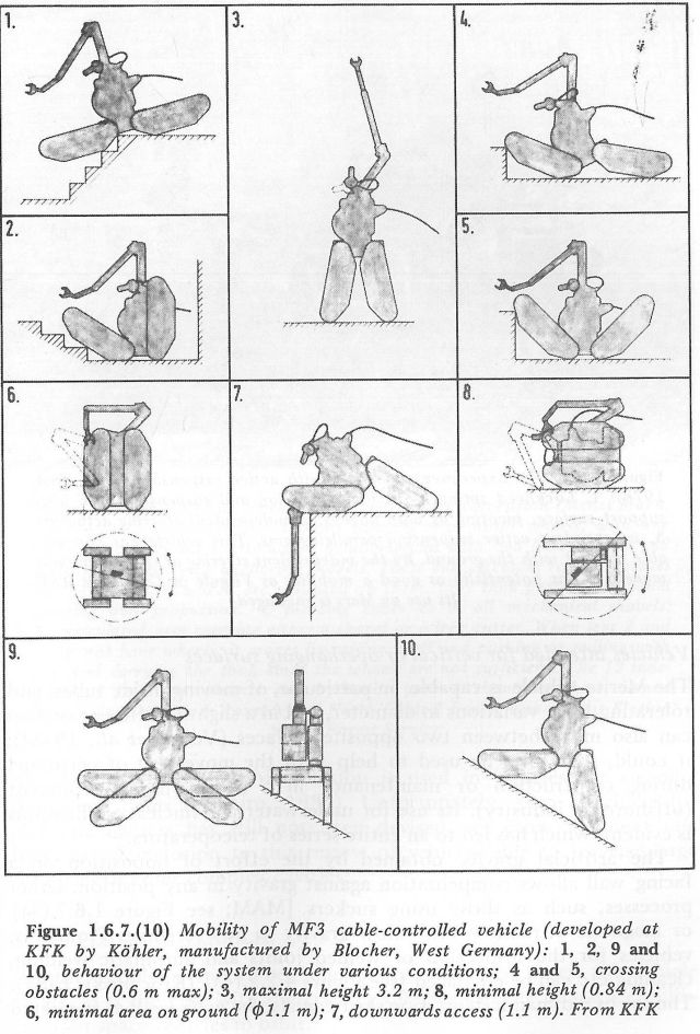
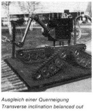
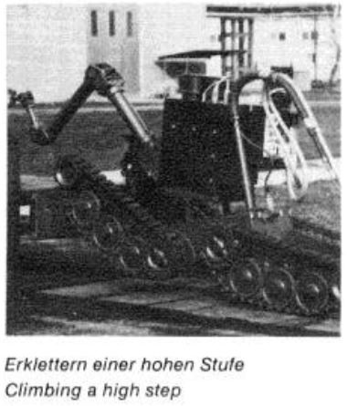
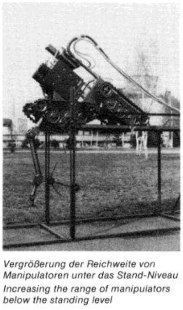
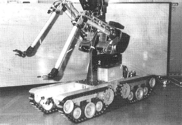
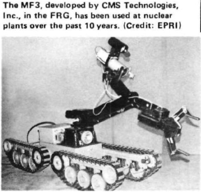
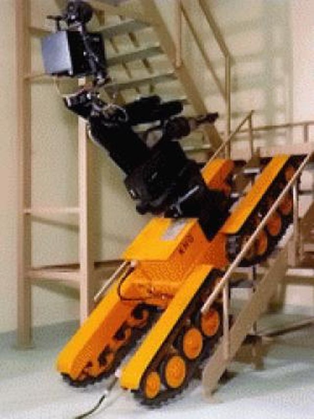
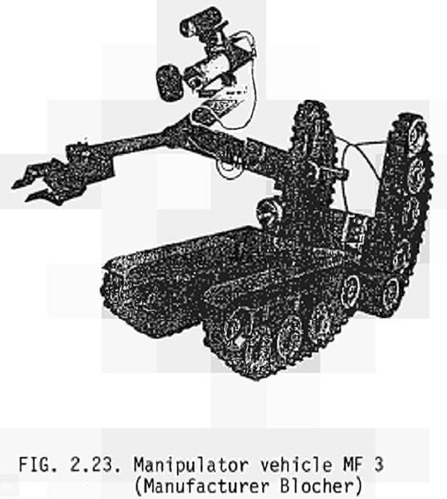
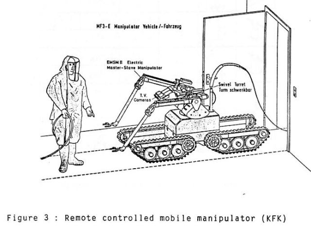
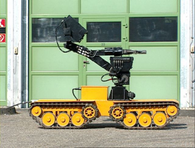
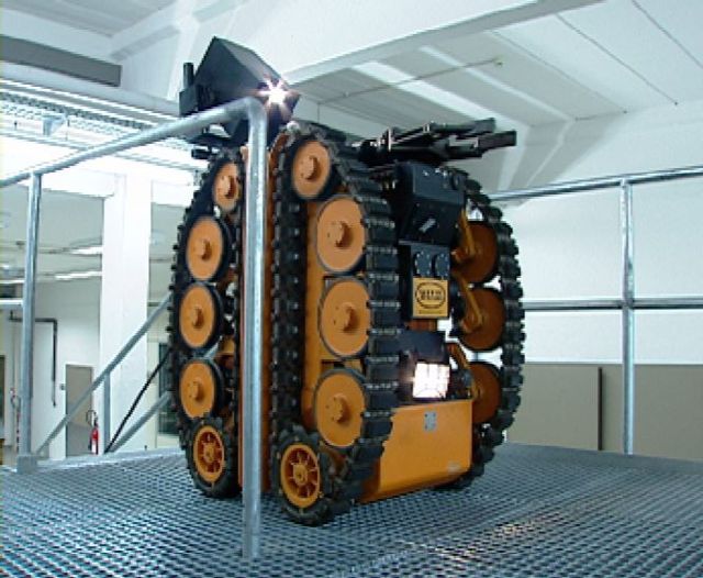
MF3
Blocher-Motor GmbH & Co. KG, Metzingen, West Germany CMS Technologies, Inc., Ft. Lee, N.J., U.S. Distributor
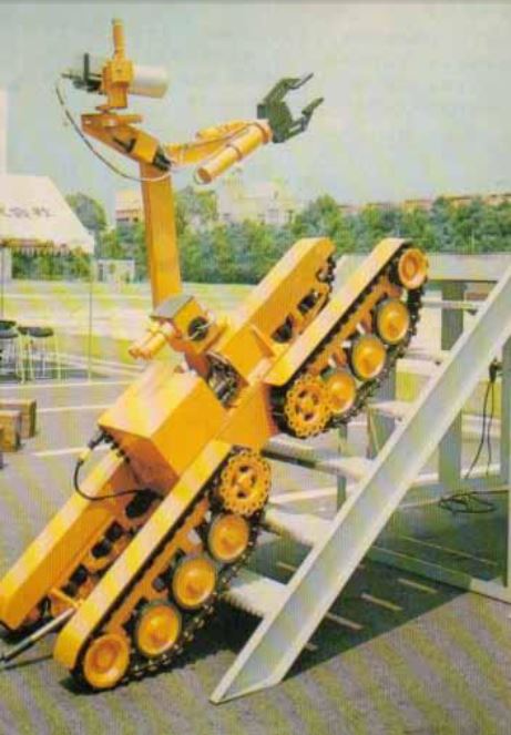
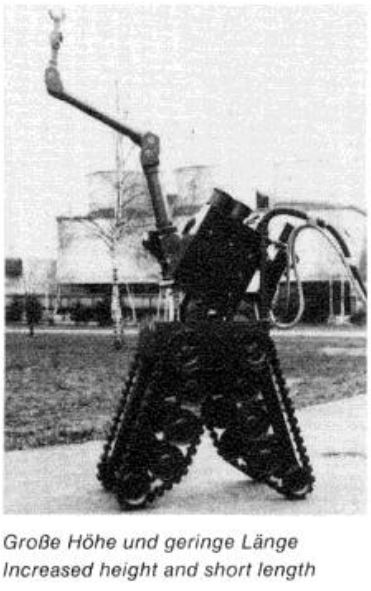
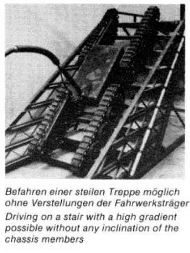
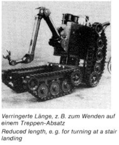
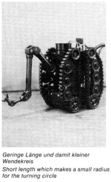
This device is a remotely controlled, tethered 4-tracked vehicle which is used in the nuclear industry and other hazardous environments. It was initially conceived and developed at the KFA Julich Research Laboratory in West Germany. Its single, light-duty, electric-powered manipulator arm can lift up to 20 kg (44 lb); the heavy-duty arm can lift up to 80 kg (176 lb). Both arms have 6 axes of movement and possess infinitely rotating long openings. Optional 7-axes electric lightweight master-slave arms (single or dual) which can perform extremely delicate operations by means of power feedback can carry 12 kg (26 lb) In a sustained operation or up to 24 kg (53 lb) in a temporary capacity. The MF3 is remote controlled from a portable control desk located up to 100 m (328 ft) from the 408-kg (900 lb) device. The MF3 dimensions are: 2264 x 720 x 400mm (1 x w x h) (89.1 x 28.3 x 15.7 in.); with track adjustment, the length and height are, respectively, 940 and 1080 mm (37.0 and 42.5 in.). It can climb stairs with a gradient of up to 45 degrees, turn on a 1200 mm (47.2 in.) radius, and can surmount 600 mm (23.6 in.) high obstacles, and traverse 1 m (3 ft) wide chasms (gaps). Its maximum speed is 30 m/min (99 ft/min), optional accessories are video cameras, TV monitor at the control desk, headlights, noise transmission system, X-ray unit with mounting arm, and alternate grippers. Power (220V, 50 Hz) and communications are made through an umbilical cord (cable). On-board electrical tools are powered through on-board sockets. An alternate model can operate with four on-board 12V batteries.
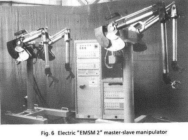
A mobile base with optional manipulator arms. The EMSM 2 arms by the same developers are shown above.