Posts Tagged ‘1971’

1971 – Model 2004 Maze-Solving Computer – Richard Browne (American)

Browne-Maze-Solver-1971-p1-x640

Source: Xenia Daily Gazette Mon, May 24, 1971

Computerized mouse maze first of 3 long-term projects for Xenian.

by Ward Pimley – Gazette staff writer

To a research psychologist, running a mouse through a maze to investigate behavior patterns is a common occurrence. But to an electronic engineering drawing specialist who wants to simulate the test, various alterations must be made.
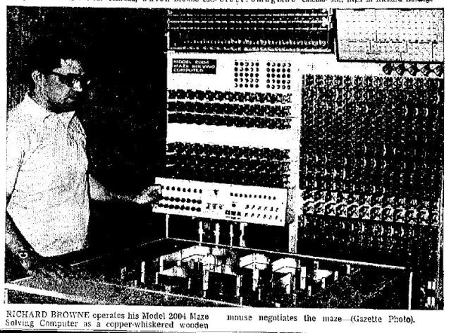
Richard Browne, a drawing specialist in his seventh year with Systems Research Laboratories, Inc. (SRL), has recently finished a lengthy project designed to propel a wooden mouse through a maze with directions being supplied by a computer. He resides at 2004 Tahoe Dr.
COMMONLY, referred to as cybernetics, the system constructed by Browne uses a computer attachment which receives data from the mouse as to its location and the presence or absence of barriers, The computer then tells the mouse which direction to move based upon the data. While the mouse is searching for its "cheese," a metal block which short circuits the electric charge upon contact, the computer is storing in its "memory" information pertaining to the maze; that is, where the alley blocks are and what routes are beneficial to the mouse's search for the goal.
CYBERNETICS is a branch of science which mechanically and electronically attempts to reproduce the human thinking process into machines. Browne's computer, designed to comply with this principle, is programmed to receive information from the mouse, "analyze" the situation, then direct the mouse on its journey. The mouse, one-inch creature carved from balsa wood, has two copper whiskers which signal the computer when the mouse has bumped into a maze barrier.
Directional information is then sent back to the mouse whereupon an electromagnet beneath the aluminum maze moves the mouse in the direction indicated. The electromagnet is driven by two one tenth horsepower engines which control both north-south and east-west movements of the mouse.
THE COMPUTER, 600 pounds of wires and relays, has the capability of processing both partial and total accumulations of "knowledge." The partial knowledge refers to the store of information regarding the squares in which the mouse has investigated, while the total accumulation is the computer's memory of the correct path the mouse should take to solve the maze. After the mouse has found the goal, it may be placed anywhere along the proper path and it will move directly to the goal without either making detours or bumping into alley walls. There is an exploration strategy which the mouse follows, Browne explained, every time it enters a square. Five steps are involved, all occurring within one-tenth of a second. The procedure is repetitive and designed so that the mouse will examine all possible avenues of escape from a square. If the mouse should encounter a wall in one direction, it then turns 90 degrees clockwise. If there is no wall in that direction, the mouse will exit the square. Otherwise, it will turn again to check a new direction. There are 25 squares on the maze with removable walls for reshaping the maze. Browne, said there are 873 duodecillion/(873 followed by 12 zeroes) solvable maze patterns possible in his operation. Should the mouse solve one million maze patterns per second (clearly an impossible task), it would take the mouse 2.7 septillion (seven zeros) centuries to solve all possibilities, Browne said.
THE PROJECT took Browne 10 years to complete, working on and off, he said. The idea for the maze came from a May 1955 issue of Popular Mechanics where an article was printed about a man who had completed such a project. Browne decided to duplicate the feat, although he designed and constructed the computer by himself. While Browne built his unit with spare parts, he said that a computer and maze constructed from new parts (and including labor costs) would cost about $15,000. The present project is completed, Browne said, except for a couple of minor improvements to be made. One of these is to put wheels on the mouse to facilitate easier movements. The other is to replace the magnet in the mouse with a stronger one so that the mouse will not escape from the electromagnet's pull from under the table.

However, Browne is not quitting his dabbling with home made electronic projects. He presently has in mind two further projects to operate from the computer he has already built. One of these is a model railroad, which Browne estimates will take him 15 years to complete (working on and off of course). The other is an electromagnetic calculator which will perform complicated mathematics.

Man's creative urge, it seems, still lives in Richard Browne.


See other early Maze Solving Machines & Robots here.


Tags: , , , , ,

1971 – Hakuyo Submersible – (Japanese)

22-3073622-hakuyo-submersible-1971-japan-x640

The Japanese Hakuyo Submersible was launched in 1971 and has one manipulator arm with five degrees of freedom.

hakuyo-71-bushby-1-x640

Image source: Manned Submersibles, Frank Bushby, 1976.

hakuyo-71-bushby-2-x640


See other early Underwater Robots here.


1965 – “Deep View” Submersible – Will Forman (American)

Deepview-1971-x640

Project initiated in 1965 headed by Willis "Will" R. Forman (seen lying down in the above image).
Launched in September 1971.
A single mechanical arm with only three degrees of freedom and claw gripper.

See Deep-View – 23:40 into the clip.

deepview-bushby-arm-2-x640

"That's a 44 1/2 -inch-diameter glass hemisphere streamlining the bow of the Navy's latest submersible, Deep View. The 300-lb. borosilicate glass dome, made by Corning, will give observers wide-angle views down to 1,500 feet-over twice the depth possible with plastic domes." Text source: Popular Science Apr 1972.

deep-view-bushby-1-x640

Project Deep View is the first submersible to incorporate glass for a significant portion of the pressure hull. It represents the first full-size manned experiment with high strength to weight transparent hulls. In a brief few years of submersible operations pilots and observers have learned the limitations of view port vision and a few have observed the maximum effectiveness obtained through transparent hulls (Sea-Link, Nemo, Kumukahi). As time continues and experience builds the glass and glass-ceramic transparent hulls continue to appear as the next step for going deeper. The difficulties in using presently available glass are due to the present low quality, brittleness and the physical properties mismatch with other high strength materials. Techniques for quantitative stress analysis were developed and comparative experiments with numerous glass to metal joints were conducted until the final design was obtained. The various subsystems are briefly described as well as the sequential testing of the pressure hull, environmental propulsion, etc. and test operations to date.
Published in: Engineering in the Ocean Environment, IEEE 1971 Conference 21-24 Sept. 1971, Page(s): 294 – 297.


The glass dome developed catastrophic cracks after repeated usage and the project was abandoned soon after. Technology at the time was not advanced enough to overcome the manufacturing problems to prevent these issues.


See other early Underwater Robots here.


1971 – Trieste II Submersible – (American)

trieste-ii-arm-2-x640

1971 – Trieste II Submersible with Manipulator Arm.

trieste-ii-arm-1-x640

DSV-1 Trieste II

When the submarine Thresher was lost on 10 April 1963, a committee established under Admiral Stephan [the Oceanographer of the Navy] to assess the implications of the accident concluded that the Navy did not have the operational assets to conduct missions in the deep sea. The loss of the Thresher was a wake up call for the Navy. A summary of the Thresher search operation in 1965 highlighting the Navy's inadequacy in deep-sea search, location, and rescue noted that the tragedy "demonstrated only too clearly the degree of ignorance and inability which surrounded the entire business."

To rectify this deficiency the Deep Submergence Systems Project, initially assigned to the Special Projects Office responsible for developing the Polaris Fleet Ballistic Missile System, was established to develop deep ocean capabilities. Subsequently other associated development programs were assigned to the Deep Submergence Systems Project office, including the development of the NR-1 nuclear powered research submarine. The intelligence community also established Deep Submergence development requirements.

A decision was made to build a second bathyscaphe, Trieste II, with the original Trieste assigned to the Deep Submergence Systems Project to test equipment that would be employed on other deep submergence systems. The new Trieste II, built at the Mare Island Naval Shipyard in September 1965, was a more sophisticated craft capable of clandestine operations in the deep ocean. DSV-1 Trieste II was designed by the Naval Electronic Laboratory, San Diego, CA, as a successor to Trieste -the Navy's pioneer bathyscaph. Trieste II incorporated the Terni, Italian-built sphere used in Trieste with an entirely new bathyscaph float-one more seaworthy and streamlined. Controlled from the pressure-resistant sphere on the underside, Trieste II was equipped with cameras, sonars, and sensors for scientific observation at great depths. Her instrumentation could be varied to suit the mission in hand. Completed in early 1964, conducted dives in the vicinity of the loss site of Thresher – operations commenced by the first Trieste the year before. She recovered bits of wreckage, positively fixing the remains as that of the lost Thresher, in September 1964.

Subsequently shipped back to San Diego, Trieste II underwent a series of modifications until April 1965, when she was launched on 19 April to undertake the first of many dives as test and training vehicle for the Navy's new deep submergence program. After a series of dives off San Diego, Trieste II underwent further modifications at Mare Island to improve the craft's undersea navigation, control, and small object recovery. When the Scorpion was lost on 22 May 1968, the previously unacknowledged Trieste II was used by the Navy to carry out the investigation.

This unique craft was listed only as "equipment" in the Navy inventory until the autumn of 1969. On 1 September 1969, Trieste II was placed in service, with the hull number X-l. Reclassified as a deep submergence vehicle (DSV) on 1 June 1971, Trieste II (DSV-1) continued her active service in the Pacific Fleet into 1980, and in May 1984 she was assigned to Submarine Development Group 1. She was moved to the Keyport Naval Undersea Warfare Center in 1985. Trieste II made dives as deep as 20,000 feet.

Source: here.

trieste-ii-sub-x640

Excerpt by Don Walsh.
Navy Electronics Laboratory (NEL) in San Diego.
Trieste was retired in 1963 at the age of ten, after it had returned to NEL from working at the site where Thresher (SSN-598) had been lost. At least two other versions of Trieste, all named "Trieste II", served with the Navy until 1982. With the retirement of Trieste II the world’s last bathyscaph was gone, since Archimede had been retired in the late 1970s

trieste-ii-sub4-x640

See 4:23 into clip.

trieste-ii-x640

Artists illustration showing another manipulator arm. This arm was commissioned when Trieste II was in DSV-1 guise [Deep Submergence Vehicle-1].

trieste-ii-sub2-x640

As well as the manipulator arm, Trieste II had a Grapple Hook mounted up front on the bow.

1971-trieste-II-sub3 - Copy-x640

trieste-ii-grapple-x640

trieste-ii-business-end-1-x640

TriesteIIEquipmentConfiguration-x640


See Trieste [I] here.

See other early Underwater Robots here.


1970-1 – CURV Mobile Linkage Manipulator – Naval Undersea Research (American)

NEVADA-CURV-Mobile-Manipulator-c-x640

1970-1 – CURV Mobile Linkage Manipulator. Originally developed for the Cable-controlled Undersea Remove Vehicle (CURV), it was adapted for potential use as a mobile nuclear manipulator as seen here. Later it was used in Bezjcy's lab at the Jet Propulstion Laboratories (JPL), along with the JPL/Ames Arm.

CURV-linkage-1-x640

CURV-linkage-x640

NEVADA-CURV-Mobile-Manipulator-x640 

The NEVADA/CURV system (Fig. 3) consists of the CURV Linkage Arm mounted on a turret which can be rotated and elevated relative to the carrier vehicle, two TV cameras for stereo viewing, a separate TV camera for monodisplay, and a remote control station with RF or hardwired link to the vehicle-arm-TV system. This hydraulically powered arm has six degrees-of-freedom, plus opening and closing the hand mechanism. The essential and novel feature of this manipulator is that it provides true linear extension by the use of an idler gear of twice the radius of a forearm drive gear. Extension is achieved by moving the upper arm with respect to the idler. The linkage action causes the course travelled by the wrist during extension to be a straight line passing through both the azimuth and elevation axes. Elevation is achieved by rotating the whole mechanism about the vertical axis of the idler. A double parallelogram added to the linkage eliminates wrist disorientation during changes in elevation and extension or the arm. Thus, the arm performs the function of positioning the hand, without disconnecting it, in a spherical coordinate system. The arm has a high section modulus which makes it rigid but lightweight. The existing prototype can handle loads corresponding to nearly 70% of the arms weight at 1.5 m extension. The control system is presently a single on-off control for each joint. Rate control servo for joystick control and position control servo for computer control are under construction. The equioment of the hand with tactile, proximity, and force/torque sensors is also in progress. Presently, the NEVADA/CURV system is used for hand-eye coordination experiments.
Source: JPL Technical Memorandum 33-721. Jan 1, 1975

See also paper by Uhrich, R., "CURV Linkage Manipulator," Naval Research Center. November 1971.

curv-arm-pat

Linear linkage manipulator arm

Publication number    US3703968 A
Publication type    Grant
Publication date    28 Nov 1972
Filing date    20 Sep 1971
Priority date    20 Sep 1971
Inventors    Richard W Uhrich, Jimmy L Held
Original Assignee    Us Navy

Abstract
A manipulator arm comprises two parallelogram linkages in combination with a trapezium linkage. The three linkage systems cooperate to produce movement in spherical coordinates when used in conjunction with three independent actuators. The two parallelogram linkages preserve spacial coordination between the wrist, elbow and shoulder joints and the trapezium linkage permits radial extension of objects carried thereby.


See other early Teleoperators here.


Tags: , , , , , , , , , ,