Posts Tagged ‘1981’

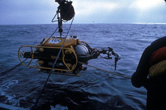
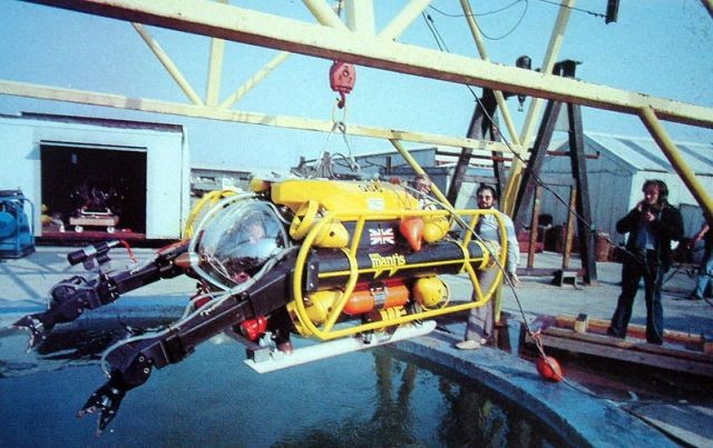
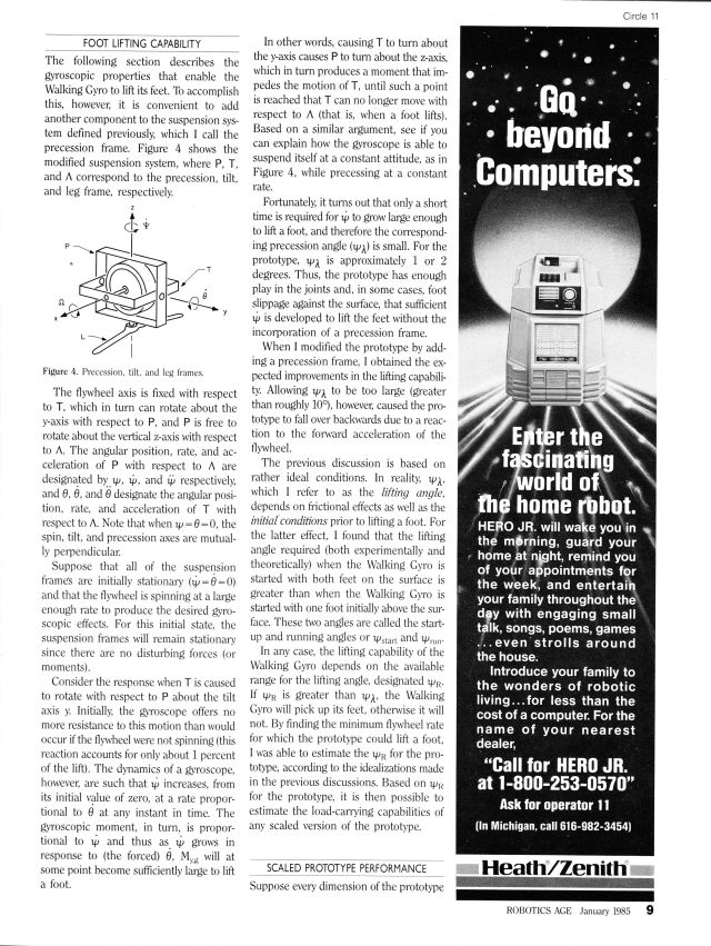
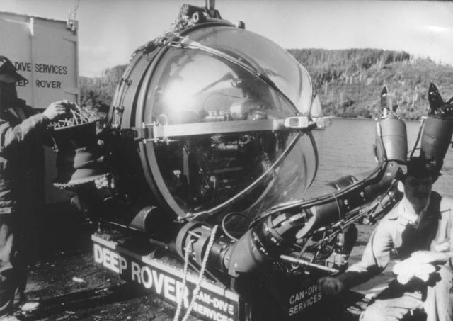
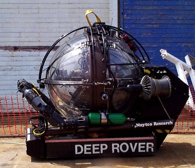
1981 – “Deep Rover” Submersible – Graham Hawkes (British/American)

deep-rover-arms-x640

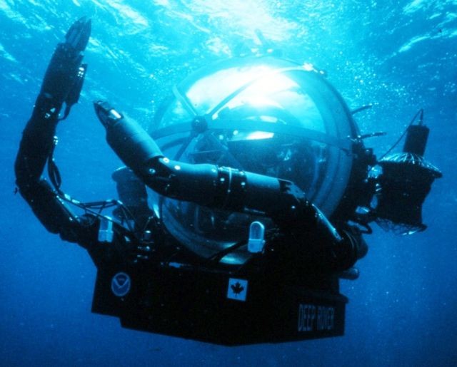
1981 – "Deep Rover" Submersible.

See 7:10 into the Video.

PM-jan85-deep-rover-x640

deep-rover-3-x640

deep-rover-4-x640

Dec84-deep-rover-2-Popular Science-x640

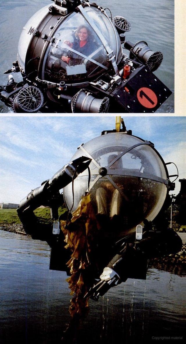
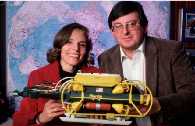
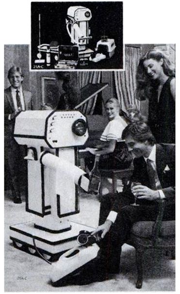
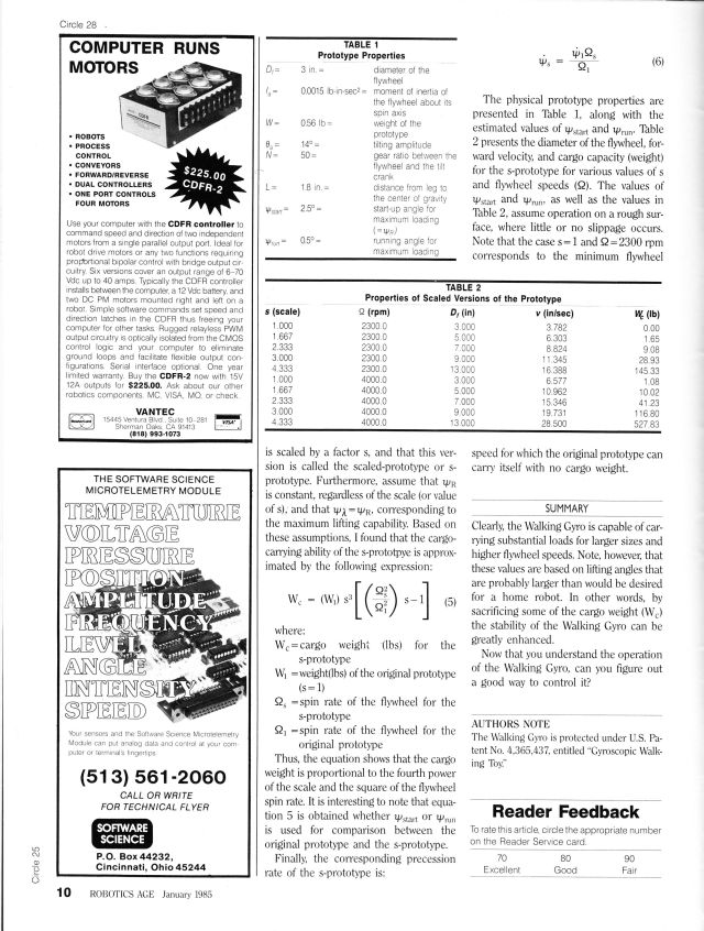
Top: Dr. Sylvia Earle. Bottom: Graham Hawkes.

Extract from Popular Science, Dec 1984.

An acrylic-bubble undersea habitat called Deep Rover will take oceanographers and oil-rig technicians to depths of 3,200 feet, where they'll work at sea-level pressure—in near-living-room comfort. The vessel "flies" like an underwater helicopter and has a set of manipulators that can lift 200 pounds apiece—or cradle an egg.

Though Deep Rover is expected to find much of its work in offshore oil fields, it was a marine biologist, Dr. Sylvia Earle, the noted oceanographic curator of the California Academy of Sciences, who planted the idea in Hawkes's mind. Three years ago she challenged him with a question: "Why can't we dive in comfort to the bottom of the ocean?" Having logged more than 4,500 hours underwater, she had the right—indeed, the need—to know. Some time later Hawkes, Earle, and Phillip Nuytten (president of Can-Dive, a Canadian company that furnishes diving support for offshore oil fields) met for dinner in Seattle. Hawkes, responding to Earle's scientific and Nuytten's commercial inputs, produced an elegant napkin sketch of the plans for Deep Rover.


MANIPS by By PETER BRITTON, Popular Science, Dec 1984.

"Manips": the human connection
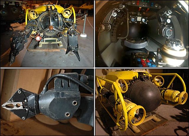
Graham Hawkes describes his work as "simplicity through complexity." Deep Rover's elegant manipulators reflect that philosophy. The official name for them is the Sensory Manipulative System. Hawkes calls them the "manips."
Their object is to extend the pilot's reach and use his unmatchable combination of intelligence, experience, depth perception; and eye-hand coordination. "We rely on the human brain rather than a computer to operate the system," says Hawkes. "If the pilot's hand is trembling, the manip will tremble in sympathy, down to about five cycles per second," he adds. The manipulators are of such dexterity and response that NASA is considering them, along with a Deep Rover-like vehicle, for excursions and work from the space shuttle.
Made of aluminum, stainless steel, and graphite-loaded nylon, the modular manipulators can vary in length from 5.6 to 7.5 feet and weigh up to 150 pounds. Each carries a light and a low-profile television camera.

Dec84-deep-rover-3-Popular Science-x640
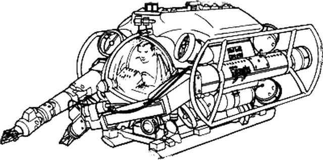
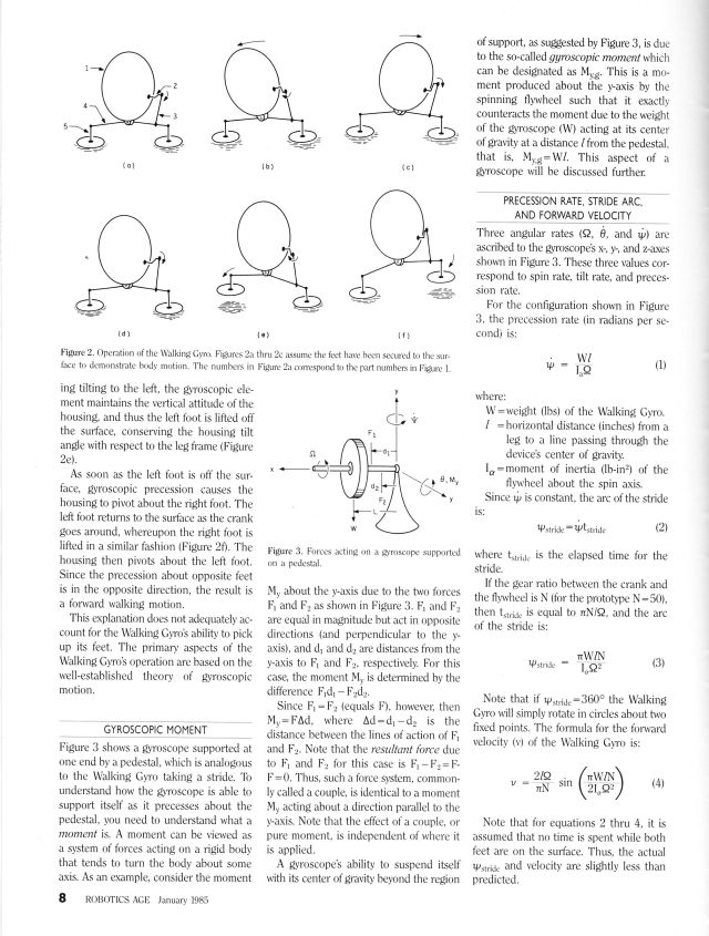
An analogy with the human arm and hand is useful in grasping the concept of degrees of freedom, and hence what the manipulators can do. An extended arm can (A) move up and down and (B) move from side to side. It can (C) bend at the elbow. The wrist can (D) move up and down, (E) move from side to side, and (F) rotate. And the hand can (G) open and close.
The complementary manipulator motions are activated through the handgrip by moving it backward and forward (resulting in action A), side to side (B), and by rotating it (C). A thumb switch on top is moved up and down (0) and side to side (E) to control the wrist. Two buttons rotate the wrist clockwise or counterclockwise (F), and a trigger opens and closes the "hand" (G).
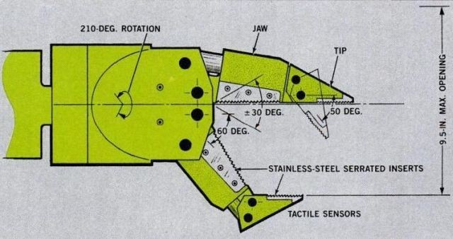
The four-function "hands" each have two large jaws and two tips. When the serrated edges of the large jaws touch an object and close on it, the force is instantly transferred to the tips, which then also close. When a four-point contact is achieved, a steady grip
occurs.
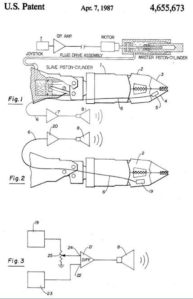
The manips employ five elements of sense (some details of which are proprietary): sight, motion, force, sound, and touch. For the manips the tactile sense is the most important. But it is not touch as we know it.
Hawkes explains: "Robots generally are designed to recreate a sense of touch by sensing remotely in the manipulator and conveying that sense to the pilot through electrical readouts. But the readouts mean nothing by themselves and must be translated. What we do is translate the tactile sense into an audio signal and feed it to the pilot through his ears.
"We're using accelerometers, and we get a sense that is analogous to the sound that comes from scraping a brick with a fork. However, we pick up not sound but accelerations in the jaw tips—vibrations, if you like."
In operation, a pilot could probe below the mud line with the manips and correctly identify whatever material he "touched," be it plastic, metal, wood, or concrete, through the sound from the cockpit speakers. A trainee, according to Hawkes, can learn this new "language" in about two hours.
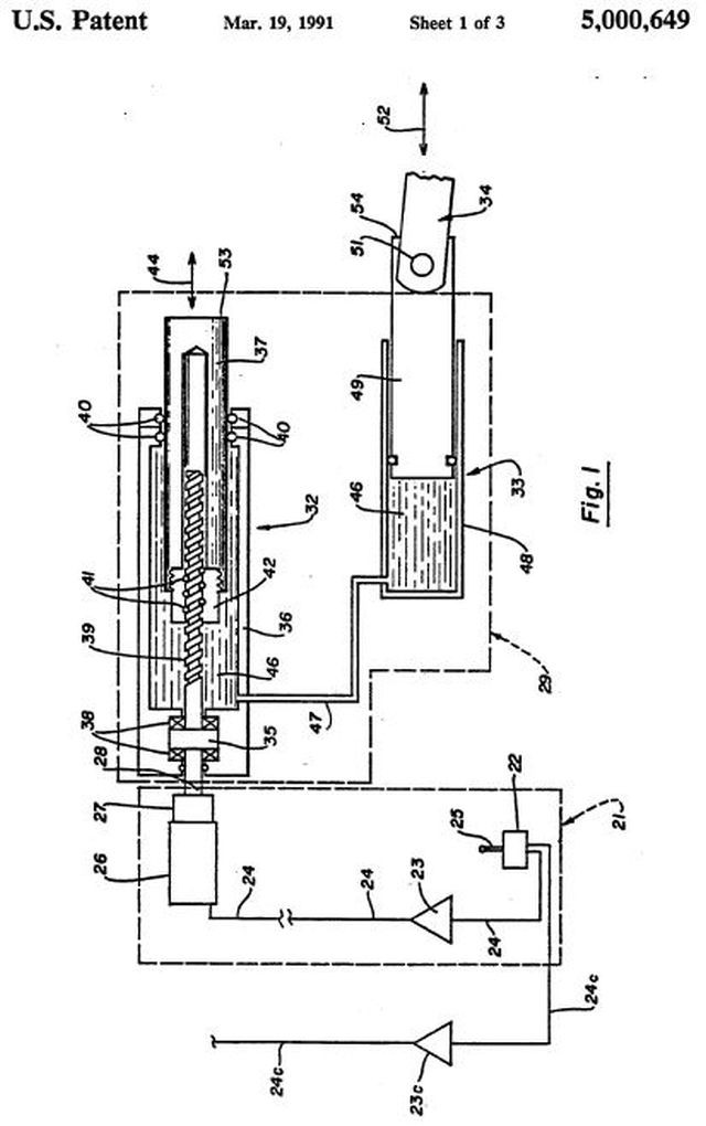
This function operates in real time, and Hawkes designed the manipulators to respond quickly—through a combination of electronics and hydraulics—so that the pilot can take full advantage of it. When the pilot commands a manip through the handgrip, he activates a motion switch built into the controller. An electrical signal goes from the controller to a power amplifier, which puts out an electrical signal that drives an actuator outside the hull. There is one actuator for every function on each manipulator.
The actuator converts the electric signal to hydraulic power through a gearbox and a lin-ear/rotary ball-bearing unit, which causes the displacement of a piston. This forces hydraulic fluid out of the actuator and into the manipulator, where a joint is moved—or a jaw is clenched. Withdrawal of the fluid causes a motion in the opposite direction.

Related Patents.

us5000649-pat1-x640
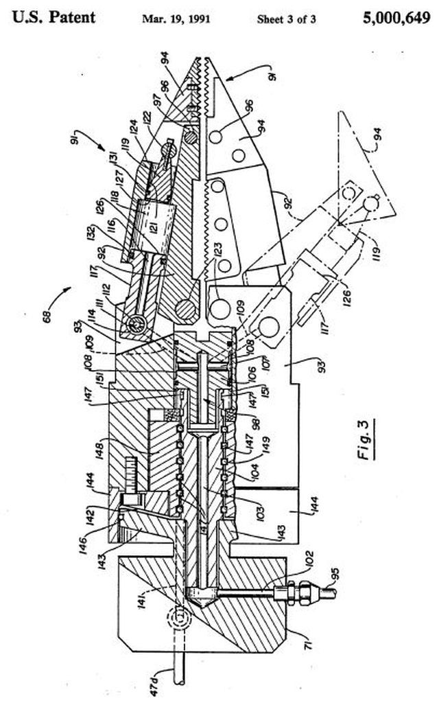
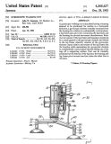
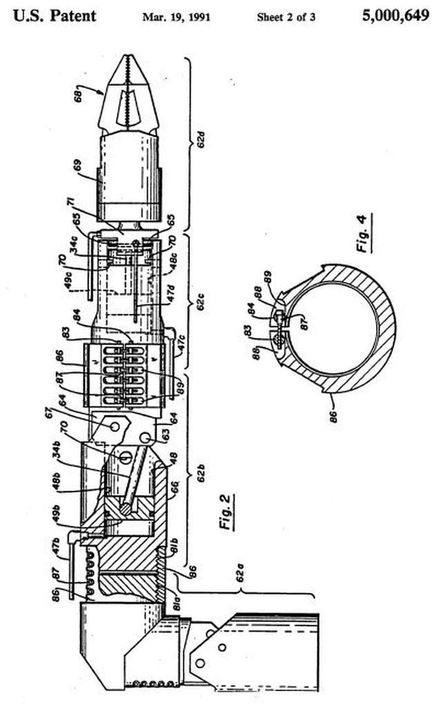
Electromechanical manipulator assembly
Publication number    US5000649 A
Publication date    19 Mar 1991
Filing date    22 Aug 1986
Priority date    15 Feb 1983
Inventors    Graham S. Hawkes
Original Assignee    Deep Ocean Engineering Incorporated

Description

This is a continuation of application Ser. No. 466,606, filed Feb. 15, 1983, now U.S. Pat. No. 4,607,798.
BACKGROUND OF THE INVENTION

The present invention relates, in general, to remotely-operated, manipulative devices and relates, more particularly, to underwater or sub-sea, remotely-controlled, powered manipulator arms.

In recent years the use of manned and unmanned underwater apparatus to explore and develop natural resources has increased dramatically. In the petroleum industry, for example, off-shore drilling has required both manned apparatus (submersibles) and unmanned underwater apparatus (robotic devices) which are capable of performing a wide variety of manipulative tasks. Typically such apparatus includes one or more remotely operated, powered arms which have a terminal device, such as claws, pincers or jaws, which are analogous to a human hand. The manipulator arms are usually jointed or have several axes of movement and may be controlled in a preprogrammed manner or by a remotely-operated input device. Such manipulator assemblies are exposed to very adverse environmental conditions, particularly when operated in bodies of salt water at substantial depths, which is the normal operating environment for most off-shore oil exploration and recovery equipment.

Prior underwater, electromechanical manipulator apparatus have typically employed a D.C. motor coupled to a hydraulic pump as the primary power for actuation or moving of the arm assemblies. The hydraulic pumps are coupled to a hydraulic circuit employing solenoid valves to control displacement of the manipulator arms and operation of the claws or jaws on the end of the arms.

If these prior art solenoid-based manipulator systems are relatively simple, the operating characteristics have been found to be poor. The smoothness and dexterity of movement with Which the arm and claws can be manipulated are not satisfactory for many applications. In order to attempt to have a smoothly operating solenoid valve- based system, the valving and pump controls can be made very complex, but the resulting complexity substantially increases cost and the incidence of breakdown.

Another prior art approach to underwater manipulative assemblies is to employ a D.C. motor-feedback servo amplifier system in which the motor directly drives the mechanical elements in the arm. Such a direct coupling of the D.C. motor to the mechanical manipulator elements has been found to require extremely close tolerances with attendant undesirable cost. Moreover, there are substantial shock loading problems in the gearboxes of such systems.

A remotely operated, underwater manipulator assembly should be capable of smooth motion over a wide speed range. Thus it should be able to move uniformly and smoothly at low speeds for precise work and smoothly at high speeds for rapid arm positioning. Underwater manipulator assemblies also should be able to exert a variable force at any of the speeds in its range of operating speeds. Moreover, a remotely operated underwater manipulator arm or assembly should have the capability of simultaneous and cooperative motion in two or more directions to give full freedom of movement of the terminal device or gripping jaws. The combination of smooth functioning over a wide speed range, variable force throughout the range, and multidirectional movement provides an underwater manipulator arm assembly which begins to closely approximate the motion and dexterity of a human arm and hand.

us5000649-pat2-x640

us5000649-pat3-x640

Additional related patents:

Publication number    US4471207 A
Apparatus and method for providing useful audio feedback to operators of remotely controlled manipulators

Publication number    US4655673 A
Apparatus and method for providing useful tactile feedback to operators of remotely controlled manipulators

us4655673-pat-x640


See other early Underwater Robots here.


1978 – “Mantis” Submersible – Graham Hawkes (British)

mantis-subm-x640

1978 – "Mantis" Submersible.

mantis-earle-x640

Sylvia Earle and Graham Hawkes.

Mantis, built by OSEL, U.K., designed by Graham Hawkes is the latest [c1978] development in the tethered submarine field. It is fitted with eight or ten electric thrusters and has two seawater hydraulically operated manipulators. The Mantis was built in 1978 and has been used for rig inspection and debris clearance operations.

submarine-mantis-48630594-x640

submarine-mantis-48631068-x640

Grahan-Hawkes-Mantis-x640

Mantis Submersible-x640

mantis001-x640


See other early Underwater Robots here.


1981 – Shinkai 2000 Submersible – (Japanese)

Research_Submersible_Shinkai_2000-x640

Model of the Shinkai 2000 showing a single manipulator with 6 degrees of freedom.

shinkai2000_img_02-x640

03-3055451-shinkai2000-4-x640

1981-shinkai2000-x640

"SHINKAI 2000" is the first manned deep submergence research vehicle in Japan, with a maximum operating depth of 2000 m and a weight of 23t. The Vehicle was designed and constructed in Kobe Shipyard and Engine Works, MHI and was delivered to JAMSTEC in Oct. 1981 after sea trials and has now engaged in deep-sea research activities after training. This paper presents the outline of design and operation including after the delivery. presents the outline of design and operation including after the delivery.

DESIGN OF "SHINKAI 2000"

"SHINKAI 2000" (the Vehicle) is carried to the area of submergence on board "NATSUSHIMA" (the Support Ship) and is supported by her in various fields such as inspection and maintenance before and after dive, launching and retrieval, positioning, tracking and communication.

Its pressure resisting structure is composed of the ultrahigh strength steel pressure sphere accommodating the crew, three titanium alloy pressure vessels storing electronic equipment and a variable ballast tank.

Main components such as batteries, distributors, hydraulic system and motors for thrusters which are of oil-filled pressure compensated type, and syntactic foam, which compensates the vehicle weight with its buoyancy, are installed in the exostructure of pure titanium and are covered then with GRP panels.

In the pressure sphere the control console for operation and monitor by one-man control, life support equipment, etc are installed. Near the seabed, searching visually, photographing, collecting samples by the manipulator, etc, are performed while observing closely through a viewport by one-man control.

Estimated time spent in the mission of 2000 m depth is 8 hours: 1 hour for launching, 1.5 hours for diving, 3 hours for seabed research, 1.5 hours for surfacing and 1 hour for retrieval. But by skilled operation, time for seabed research can be increased by decreasing time for other phase operations.

Source: here.


See other early Underwater Robots here.


1981 – ComRo I – Jerome Hamlin (American)

Comro I with Vacuum Cleaner accessory.

Above: ComRo I with the robot pet, Wires.

(Text: Circa 1981)

A bit more utilitarian than robots serving drinks or selling products is Jerome Hamlin's ComRo I. This robot made its debut in the latest Neiman-Marcus Christmas catalog. It operates two ways, by hand-held remote control, or by a programmable microcomputer in the robot's head. ComRo I could make life a little easier with its built-in vacuum cleaner, wireless telephone, digital clock, black and white TV, and manipulator arm that can lift up to 10 pounds. The price for such ease, however, is $15,000.

But its purpose really isn't to make life easier, says Mr. Hamlin, who built ComRo I in an abandoned garage. ''It's basically a toy–more recreational than practical.'' So far, Hamlin has sold two ComRo I's to Japan and one to Saudi Arabia. The product may be more technologically advanced than the other robots, but its sales seem to be trailing in the dust.


DOMESTICATING THE ROBOT FOR TOMORROW'S HOMES By PETER APPLEBOME  Published: The New York Times, March 4, 1982

For those who are not choosy about semantics, the age of the home robot is already here. Last Christmas Neiman-Marcus offered a $15,000 robot that, the depart-ment store said, could open doors, walk the dog, take out trash, water plants and sweep floors. Playboy's publisher, Hugh Hefner, owns a $20,000 robot built by the Android Amusement Corporation of Monrovia, Calif., outside Los Angeles, that can greet guests, disco at parties and ferry drinks.

Revelers at Billy Bob's Texas, a mammoth country and western complex in Fort Worth, were recently joined by Sheriff Bud Longneck, a 7-foot-8-inch walking Budweiser beer can decked out in a flannel shirt, cowboy boots, cowboy hat, neckerchief and badge.

They are all great attention-getters, but they are not true robots. A robot is defined as a multifunction device equipped with artificial intelligence that can be programmed to perform various tasks. Mr. Hefner's robot and Sheriff Longneck are what are known as showbots, radio-controlled contrivances operated in much the same way as model airplanes. The Neiman-Marcus robot, ComRo I, does have a microcomputer that allows it to function as a robot, but all the tasks it is supposed to perform are done by radio control.

In the grand tradition of his-and-hers camels, ostriches and submarines, Neiman-Marcus's robot was not exactly a hot seller. So far only two have been sold – one to the Mitsubishi Electric Corporation of Japan and one to the head of a Saudi Arabian importing concern. Neiman-Marcus also sold four of the robot's $650 radio-control robot pets, Wires.

Neiman-Marcus officials insist, nonetheless, that the robot was a tremendous success as an attention-getter. ''We probably got more response to it than anything we've done in the Christmas catalogue in the last 10 to 15 years,'' said Tom Alexander, vice president of marketing and sales promotion.

Many large corporations such as General Electric have researchers looking into home robotics. As with home computers, much of the real exploratory work is being done by entrepreneurs such as Jerome Hamlin, whose ComRo Inc. of Danbury, Conn., produced the Neiman-Marcus robot, or Gene Beley, whose Android Amusement Corporation made Mr. Hefner's.


See more of the ComRo family of robots : "Bumpy", "Tot" and "Bubble Tot". (to to updated when posts available)


See other early remote-controlled and robotic vacuum cleaners and floor scrubbers here.


Tags: , , , , , , , ,

1981 – The Walking Gyro – John W. Jameson (American)

The Walking Gyro was conceived and built by John Jameson in 1981. 

Article Source: Robotics Age, January 1985.

THE WALKING GYRO

John W Jameson
275 E. O'Keefe #7 
Palo Alto, CA 94303

Walking machines generally fall into one of two categories: statically balanced or dynamically balanced. A statically balanced machine maintains stability at every position in its stride by always keeping its center of gravity aboye the region of contact between the machine and the surface.                       

A dynamically balanced machine is generally not statically stable at every stride position and must rely on intermittently applied control forces in order to keep upright. The Walking Gyro seems to fit best into the latter category, but its simplicity relative to other forms of dynamically stabilized walking machines makes it an attractive alternative for home experimentation.
                                                                   
Two characteristics are readily observed by experimentation with any toy gyroscope. One is the gyroscope's inherent stability, as illustrated by its ability to stay upright while keeping only one point in contact with a supporting surface. Another is the counter-intuitive reaction the device exhibits when the gyroscope is twisted about an axis perpendicular to the flywheel spin axis. The Walking Gyro utilizes both characteristics plus a third, gyroscopic precession, to provide a walking mobility base.

Although I have not yet constructed a model of the scale desirable for an experimental home robot, my analysis of the Walking Gyro's dynamics indicates that such a device is feasible. In fact, the analysis indicates that the stability and load-carrying capabilities increase dramatically with scale. Although the principies of the Walking Gyro are somewhat complicated, the basic mechanism is quite simple. Adding velocity and direction control offers a challenging (though not necessarily complicated) task for the home experimenter.  

The Walking Gyro utilizes the angular momentum of a spinning flywheel to perform the following functions: lift the feet, balance during the stride via gyroscopic reaction torque, and move forward via gyroscopic precession. My prototype, shown in Photo 1, is powered by a hand crank and relies on  energy stored in the flywheel to sustain motion.
Figure 1 shows a side view, partially sectioned, of a Walking Gyro in mid-stride.  The housing (1), which contains the flywheel (2), and the gear train (3), is caused to tilt back and forth with respect to the  leg frame (4) by the crank (5) and link (6).                                    

This motion is about the fore-and-aft pivot (7). The legs (8) are attached to the leg frame by the fore-and-aft pivots (9) and the feet (10) are attached to the legs by the vertical pivots (11). Finally, the horizontal bar (12) connects to both legs by the fore-and-aft pivots (13) so that they stay parallel. Note that in this particular presentation, the mechanism is equipped with an adaptor for a crank (14), which is used to bring the flywheel up to operating speed.

SIMPLE EXPLANATION

Caption  Photo 1. The Walking Gyro caught in mid-step.

Figure 2 details the mechanism's movements. Figure 2a shows the Walking Gyroscope in a neutral position. Figures 2b and 2c show the motion that would occur if the feet were somehow attached to  the walking surface. Figure 2b shows the housing tilting to the left, and Figure 2c shows a tilt to the right. Figures 2e and 2f show what happens if the same conditions of Figures 2b and 2c occur but with the feet free to move. Instead of the housing tilting to the left, the gyroscopic element maintains the vertical attitude of the housing, and thus the left foot is lifted off the surface, conserving the housing tilt angle with respect to the leg frame (Figure 2e).
As soon as the left foot is off the surface, gyroscopic precession causes the housing to pivot about the right foot. The left foot returns to the surface as the crank goes around, whereupon the right foot is lifted in a similar fashion (Figure 20. The housing then pivots about the left foot.
Since the precession about opposite feet is in the opposite direction, the result is a forward walking motion.
This explanation does not adequately account for the Walking Gyro's ability to pick up its feet. The primary aspects of the Walking Gyro's operation are based on the well-established theory of gyroscopic motion.

Figure 1. Cross-section of a slightly altered form of the prototype Walking Gyro.

See images for rest of article.


See full patent details here.

Patent number: 4365437
Filing date: Apr 15, 1981
Issue date: Dec 28, 1982


Toys based on Jameson's patent.

Remote-control to move robot in different directions.

"Hitch Hiker" Walking Robot.

Showing the insides of the "Hitch Hiker" version.

walking-gyro-toy-x640

WalkingGyros-1


Meccano model of The Walking Gyro.

The Meccano model on the right was built by Bernard Perier from a Meccano set. Gyroscopic reaction force causes lifting of the feet and gyroscopic precession drives the motion forward.

(photo by Stefan Tokarski)


Gyroman 3D-printed by by Jeff Kerr from Make Magazine.

gyroman-1

gyroman-2

gyroman-3


It would be great to see a scaled-up one of these at Burning Man with the driver as the payload.

**Update July 2015 – There’s a rumor that the original designer, John Jameson, is considering a giant, rideable version of Gyroman.


See also the Gyrocycle.