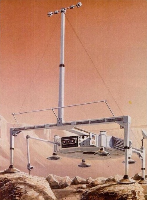
Frame walkers are a class of mobile robots that are robust and capable mobility platforms. Variations of the frame walker robot are in commercial use today are: Komatsu Ltd. of Japan developed the Remotely Controlled Underwater Surveyor (ReCUS) and Normed Shipyards of France developed the Marine Robot (RM3). Both applications of the frame walker concept satisfied robotic mobility requirements that could not be met by a wheeled or tracked design. One vehicle design concept that falls within this class of mobile robots is the Walking Beam, illustrated in Figure 15-8. For NASA’s Mars Rover Sample Return Mission, it entails a mobile robot that can travel from its lander to geographically interesting sites and return samples. The more interesting the site, the greater the hazards anticipated. The rover will have at most 1 year to make all its traverses. There are four explicit requirements for the rover: 1) Cross a 1-meter ditch, 2) negotiate a 1-meter slope, 3) climb a 60% grade hard surface, and 4) climb a 35% grade loose, sandy surface. Reliability and safety is paramount to the success of this mission. To demonstrate the capabilities and usefulness of a frame walker as a rover, a working model was built.
An one‑quarter scale prototype of the walking beam was built in 1989 by Martin Marietta to evaluate the potential merits of utilizing the vehicle as a planetary rover. The initial phase of prototype rover testing was structured to evaluate the mobility performance aspects of the vehicle. Performance parameters such as vehicle power, speed, and attitude control were evaluated as a function of the environment in which the prototype vehicle was tested. Subsequent testing phases will address the integrated performance of the vehicle and a local navigation system.
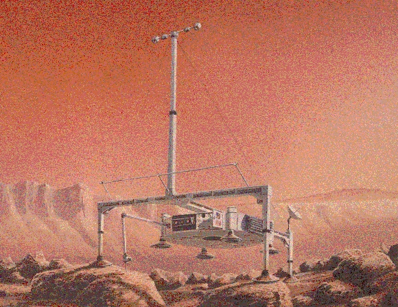
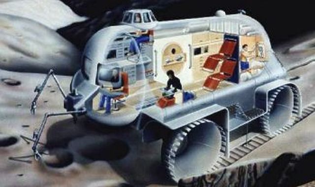
Figure 15-8. Artist Concept of the Mars Rover called the Walking Beam
An one‑quarter scale version of a planetary rover concept, the "walking beam", was developed to evaluate a variety of vehicle performance parameters. Prior to construction and testing of the prototype, the only performance predictions that were available for this version of the walking beam concept were those produced by computer simulations utilizing invalidated mobility models. Empirical test data to be used in the validation of vehicle performance modeling parameters was generated through actual testing of the hardware prototype. In addition, valuable insight was gained into the strengths and weaknesses of the walking beam.
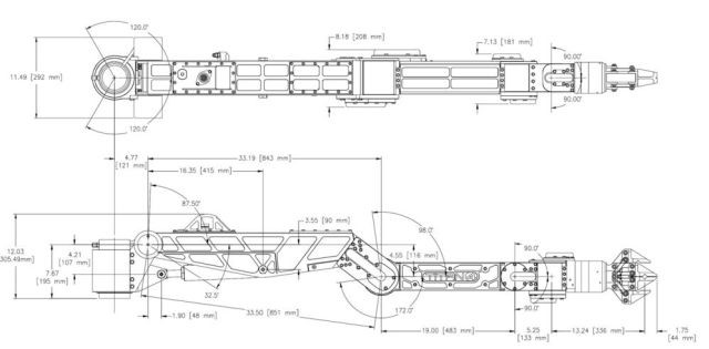
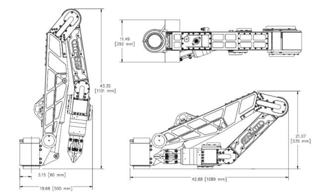
The walking beam prototype is a mobile robot that uses two platforms that alternately translate one with respect to the other, to propel it. It stands 0.9 meters high (with legs fully retracted) and is 1.5 meters wide by 1.5 meters long, and weighs 163 kg (see Figure 15-9). The walking beam has two major hardware subsystems, the upper T‑beam assembly and the lower payload assembly. There are seven legs, all of which actuate in the vertical direction only. The legs are grouped into two sets: a quadruped inner base supporting the lower payload assembly, and a tripod outer base supporting the T‑beam assembly. In addition to the seven legs, there is a translation system for locomotion and a rotation system for steering. All together, there are nine actuators, one for each of the degrees of freedom.
To provide the data necessary to control the rover and monitor its performance, the vehicle was equipped with position sensors for all nine degrees of freedom, motor current sensors, roll and pitch inclinometers, and ankle load cells. A second order low pass filter was used on each sample channel to provide the necessary noise filter and antialiasing required for the sampled sensor signals. Control of the vehicle is accomplished utilizing a manual control box or a real‑time control computer, both of which communicate with the rover through umbilicals.
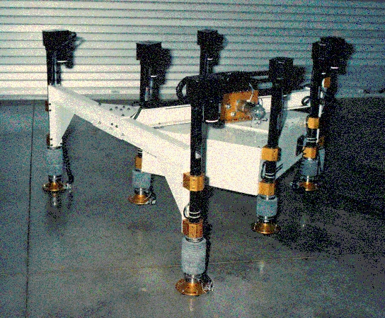
Figure 15-9. Prototype Walker (Courtesy of Lockheed Martin)
The prototype rover utilizes nine identical motor controllers, one for each motor. The motor control card accepts low power differential control signals from the computer interface or the manual control box and drives the motors with currents of up to 10 amps peak. Pulse width modulation is used in the motor control circuitry to maximize efficiency while keeping power dissipation to a minimum. Each motor controller can be set to operate in one of three modes: position servo, velocity servo, and voltage amplifier.
Three voltage levels are provided on the prototype vehicle, ± 15 volts at 6 amps for electronics power, and 24 volts at 40 amps for motor power. Provisions were made for instant interruption of the 24-volt motor power supply, should control of the vehicle be lost. Kill switches were provided on the manual control box and at the control computer to interrupt motor power when needed.
The prototype vehicle footpad design is a 15-centimeter diameter inverted cone, intended to emulate a camel's foot. The inverted cone shape is designed to operate efficiently and reliably in dry loose soil as well as on rocky terrain. Provisions were made in the design of the sole of the foot to allow experimentation with different sole configurations. Attached directly to the footpad is a compression load cell rated at 114 kg. By monitoring the load cell outputs, the control software is able to determine when a foot contacts the surface and what portion of the vehicle weight is being carried by each of the legs. This information is especially useful for maintaining stable support with the quadruped base.
Each of the ankles of the prototype can be configured in either a spring-loaded, compliant mode or by replacing the spring with a metal tube, a rigid mode. Testing was scheduled to ascertain which ankle configuration offers the best vehicle mobility performance for the greatest diversity of terrain.
Motion of the prototype vehicle is accomplished with a sequence of six steps (see Figure 15-10). The six steps in a normal translation sequence are as follows: 1) raise the inner base legs, 2) translate the inner base, 3) lower the inner base legs, 4) raise the outer base legs, 5) translate the outer base, 6) lower the outer base legs. Rotation of the vehicle is accomplished with the same sequence of six steps, substituting rotation of the bases for translation in steps 2 and 5.
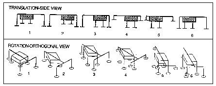
Figure 15-10. Vehicle Operations
The attitude control system of the walking beam has the capability of operating with the vehicle body parallel to the mean surface slope, operating with the vehicle body in a level attitude, or operating with the vehicle body at an arbitrary attitude selected by the operator. The level vehicle and surface parallel modes are illustrated in Figure 15-11. Each approach has advantages and disadvantages when the vehicle is operating on an incline. On the plus side, the surface parallel mode provides maximum translation stroke and minimum leg extension requirements, but is more susceptible to tip over and larger side loads are applied to the vehicle legs. The level vehicle mode maintains a larger tip over safety margin and does not exert as large a side load on the legs, but has a reduced translation stroke and is limited to a 14° slope compensation by the outer base leg stroke. A fourth attitude control mode that maintains each leg group at equal lengths, was incorporated for vehicle check out and characterization purposes.
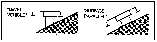
Figure 15-11. Slope Negotiation Modes
In addition to controlling the prototype vehicle’s orientation and compensating for uneven and inclined surfaces, the attitude control software is responsible for maintaining a minimum ground clearance of the raised legs and maintaining surface contact for the lowered legs. As the vehicle traverses an uneven surface it must continually update the leg position commands to maintain the required ground clearance. When the quadruped (inner) base of the vehicle is providing support, the software must adjust for the fact that the four-point support may be indeterminate. All three of the constraints, orientation, ground clearance, and surface contact, are factored into the leg position control commands of the prototype attitude control system.
Prototype leg control is accomplished with three modes. The first mode is a position command mode in which the leg position sensor is used to provide closed loop control of the leg position. The second mode is a surface search mode in which the leg is extended at a constant rate until the surface is reached as indicated by the ankle load cell. The third mode of leg control is the load search mode. In this mode, the leg length is adjusted until the leg as measured by the ankle load cell is carrying the desired load.
A path follower controls vehicle motion with respect to waypoints. The path follower subsystem is responsible for executing the commanded way-point sequence as defined by the operator. Way point commands are given to the path follower routine in the form of destination point Cartesian coordinates or path segment length and compass heading or path segment length and delta heading. The path follower will then cycle through the rotation sequencer and translation sequencer to move the vehicle along the path way points. As the vehicle is traversing the commanded path, its calculated position is compared against its desired position. If the vehicle has strayed from the desired path, corrections are made to the commanded vehicle heading and path length at each waypoint to bring the vehicle back on track. Table 15-4 summarizes the control modes of the prototype vehicle.
Table 15-4. Different Control Modes
TYPE OF CONTROL
CONTROL MODES
Leg Control
• Position Command
• Leg Load Command
• Surface Search
Attitude Control
• Level Vehicle
• Surface Parallel
• User Defined
• Constant Leg Length
Path Control
• Cartesian Coordinates
• Path Segment Length and Compass Heading
• Path Segment Length and Delta Heading
Results from the testing of the one‑quarter scale vehicle show it is able to achieve an average speed of 2.4 cm/sec while maintaining a 7-cm minimum ground clearance and 1.9 cm/sec while maintaining a 15 cm minimum ground clearance. The net speed of the vehicle is directly affected by the minimum ground clearance maintained by the vehicle. Translation speed of the inner and outer bases of the prototype is relatively constant at 7 cm/sec. Extension and retraction speed of the legs is relatively constant at approximately 4 cm/sec. Therefore, the net vehicle speed is controlled by translation stroke distance and the extension and retraction distance of the legs.
Prototype power utilization was analyzed by evaluating the power needs of the vehicle as it performed standard maneuvers. Figure 15-12 shows the power consumption of the vehicle during one complete translation sequence for a traverse of a level surface. The power utilization of the vehicle was broken out by inner base legs, outer base legs, translation motor, and total vehicle usage. Each of the six translation sequence steps described previously is indicated on the chart. The peak power requirement for this maneuver was 158 watts and the average power requirement was 66 watts. Figure 15-13 shows the power consumption of the vehicle while ascending a 13° incline using the surface parallel attitude control mode. As was expected, the power requirements for the translation motor went up. Leg motor power usage also went up due to the increased side loads on the legs resulting from the use of the surface parallel mode on an incline. The peak power usage for the 13° incline traversal was 205 watts and the average power consumption was 135 watts.
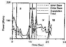
Figure 15-12. Level Surface and 7-cm Clearance.
Local navigation test results show that the rover is very good at dead reckoning in translational motion. Problems with the rotation sensor limited the ability of the rover to maintain accurate information about it's heading. While performing translational maneuvers only, the vehicle had position errors less than 0.25% of the actual measurements. The rotational sensor (a potentiometer which measures the relative angle between the inner and outer base of the vehicle) displayed a measurement hysteresis of approximately 1.5° and as a result, was of little value in maintaining useful information about vehicle heading. The vehicle attitude is monitored by ± 60° roll and pitch inclinometers that displayed excellent linearity and freedom from cross axis coupling. Errors introduced by inclinometer uncertainties were well below the communication quantization levels of sensor signals. Extensive analysis of the vehicle’s ability to perform dead reckoning awaits planned upgrades to the rotation position sensor.
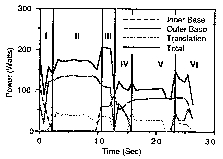
Figure 15-13. 13° Incline and 7-cm Clearance
Results of the attitude control analysis tests indicated that control of the vehicle attitude was maintained within .75° rms of the desired attitude in both the pitch and roll axes. Planned upgrades to the controller software should be able to improve the vehicle attitude stability significantly, although it is not certain at this point that vehicle attitude stability much greater than the level already achieved will be necessary to support vehicle operations.
Testing was conducted of the attitude control subsystem's ability to establish a stable four-point support for the inner base leg group. The indeterminate condition of four-leg support requires additional leg control logic that is not required for the tripod leg group. Figure 15-14 is a time history plot of the load profiles for the inner base legs as the attitude control system seeks to establish a stable four-point configuration. In most cases, the inner base feet will contact the surface at different times as the legs are being lowered. As each foot contacts the surface, the attitude control system changes the leg control mode being used for each leg. After all four feet are on the surface, it then establishes a stable load distribution among the four legs. Testing indicates that the attitude control system is able to find a stable solution to the indeterminate problem but there is room for improvement in the response time of the controller.
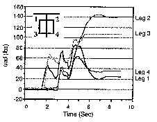
Figure 15-14. Load Profile for the Inner Set of Legs
Test results obtained to date indicate that the walking beam concept functions as predicted. The first phase of testing did not revealed any significant design deficiencies that might eliminate the walking beam concept as a potential candidate for the planetary rover missions. Test activities have included several different vehicle evaluations, with ongoing plans to continually expand the nature, difficulty and complexity of the vehicle’s test environment. As testing proceeded, the performance data obtained from the vehicle continued to provide an expanding picture of the functionality of the Walking Beam concept. This effort ended with the Sojourner Rover being picked as the baseline for the Mars Pathfinder Mission, which landed in 1996.
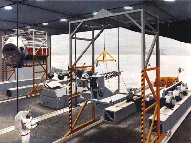
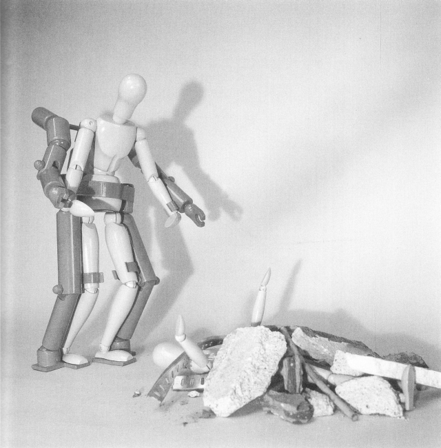
Above text and images supplied by Wendell Chun himself, 2010.
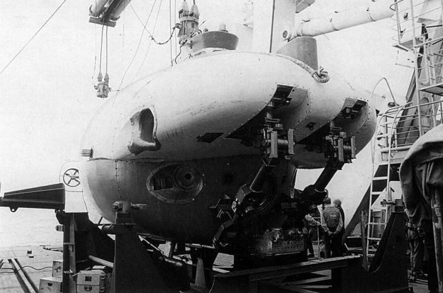
-x640.jpg)
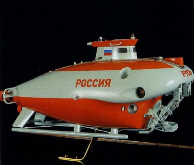
Model of Walking-Beam Mars Rover.
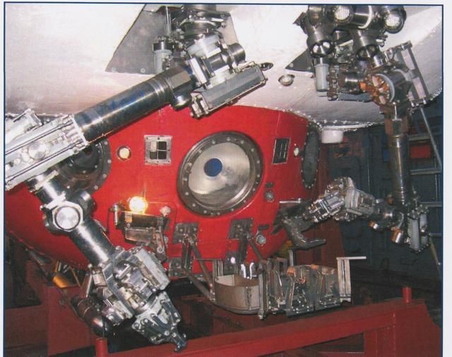
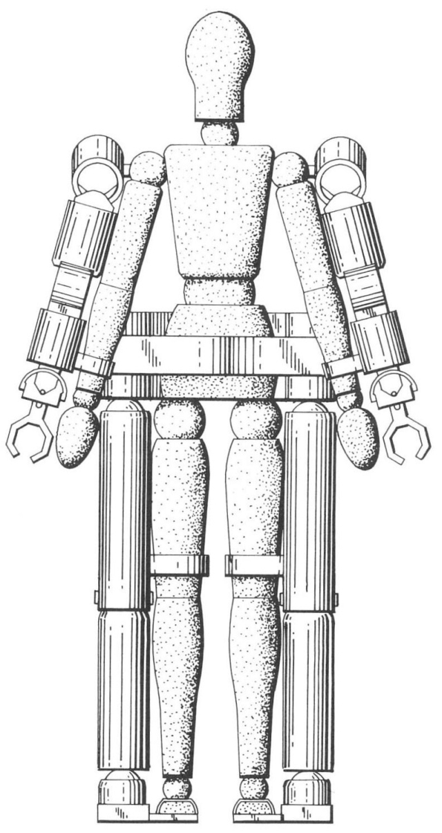
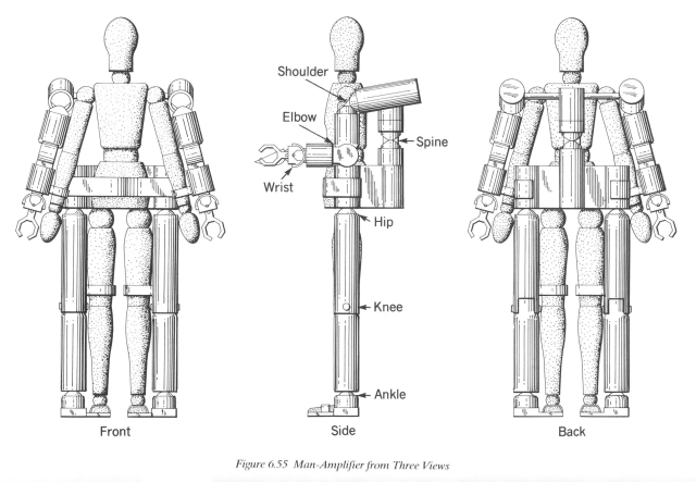
-x640.jpg)
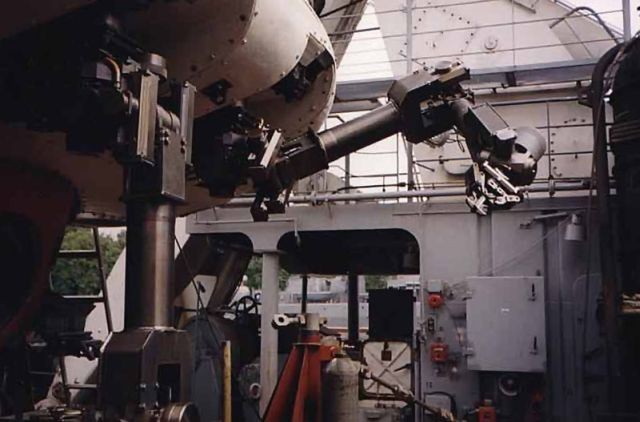
-x640.jpg)
The above images sourced from Mark Rosheim's book Robot Evolution.
See pdf on Stability Analysis by Barghava and Waldron here.