Posts Tagged ‘Ivan E. Sutherland’

1953 – “Franken” Maze-Solving Machine – Ivan and Bert Sutherland

FRANKEN

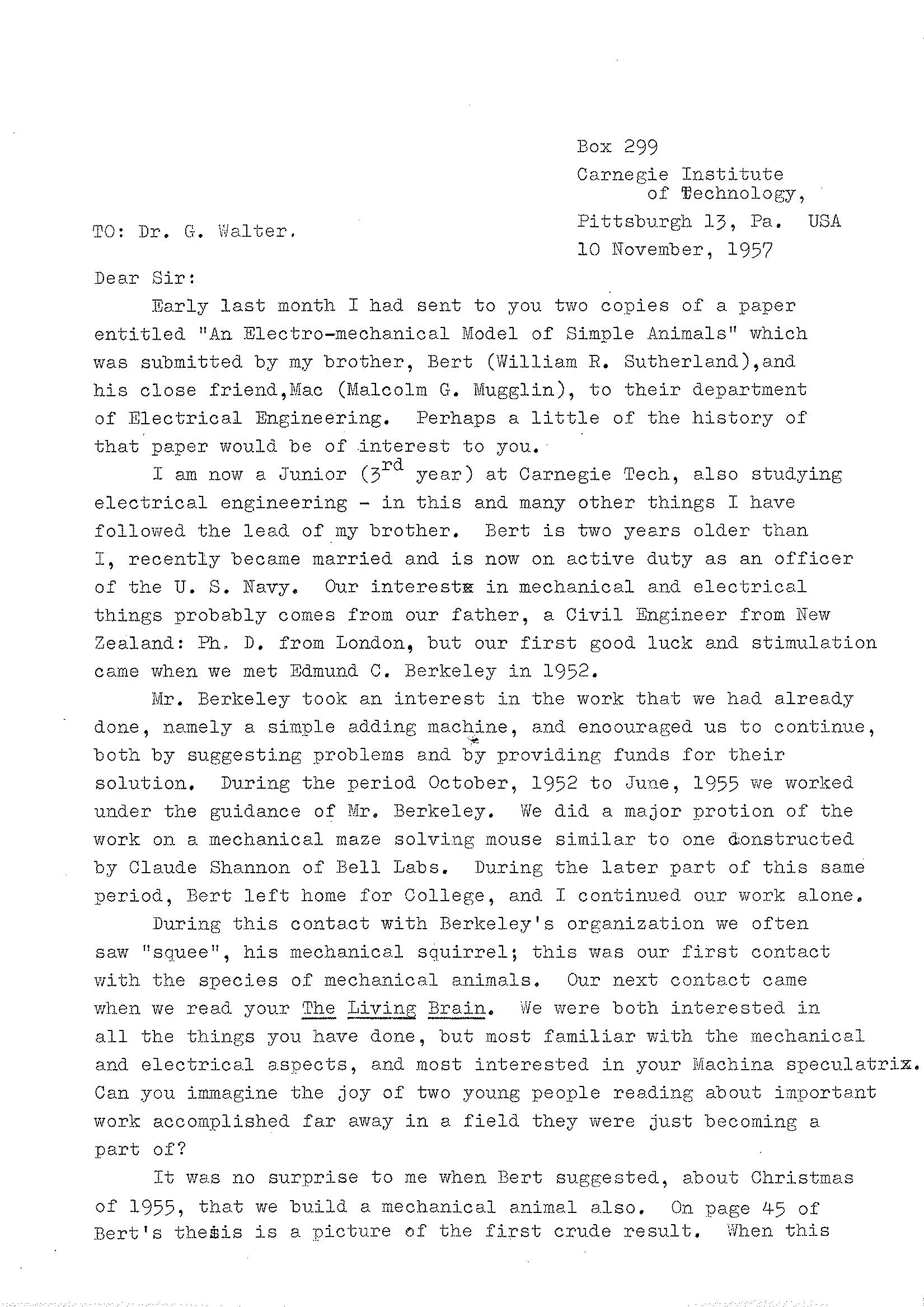
The original Franken maze solver was designed and built by Bert and Ivan Sutherland. I suspect it was built for Edmund C. Berkeley.  Berkeley , it appears, had used the early version as a prototype, and engaged his other associates, namely Bob Jensen, Juli Skalski and Stan Skalski in drawing up a revised document suitable for sale as plans, kits, or small-scale production in 1957.

Above pdf has notes Franken made by Bert Sutherland as sent to Ed Berkeley.

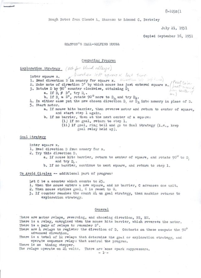
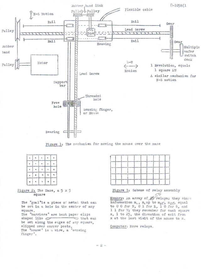
Berkeley's internal memorandum on Franken, The Maze-Solving, Food-Getting, Learning Beast was based on Claude Shannon's earlier 1951 Maze solver using a sensing-finger rathjer than a magnetically controlled mouse.

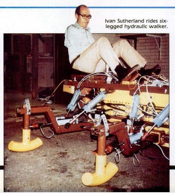
Ivan and Bert Sutherland first started designing Franken in 1951. The prototype appears to have been built around 1953, if not earlier, according to a letter by Bert Sutherland to Ed Berkeley.. Improvements were was later suggested by Ivan Sutherland (see pdf below). 

It was finally handed over to Ed Berkeley in May, 1955.

[Note: Claude Shannon was later Ivan Sutherland's Thesis supervisor.]

See Claude Shannon's note on Maze construction considerations to Ed Berkeley here.

From Edmund C. Berkeley's SMALL ROBOTS — REPORT, 1956

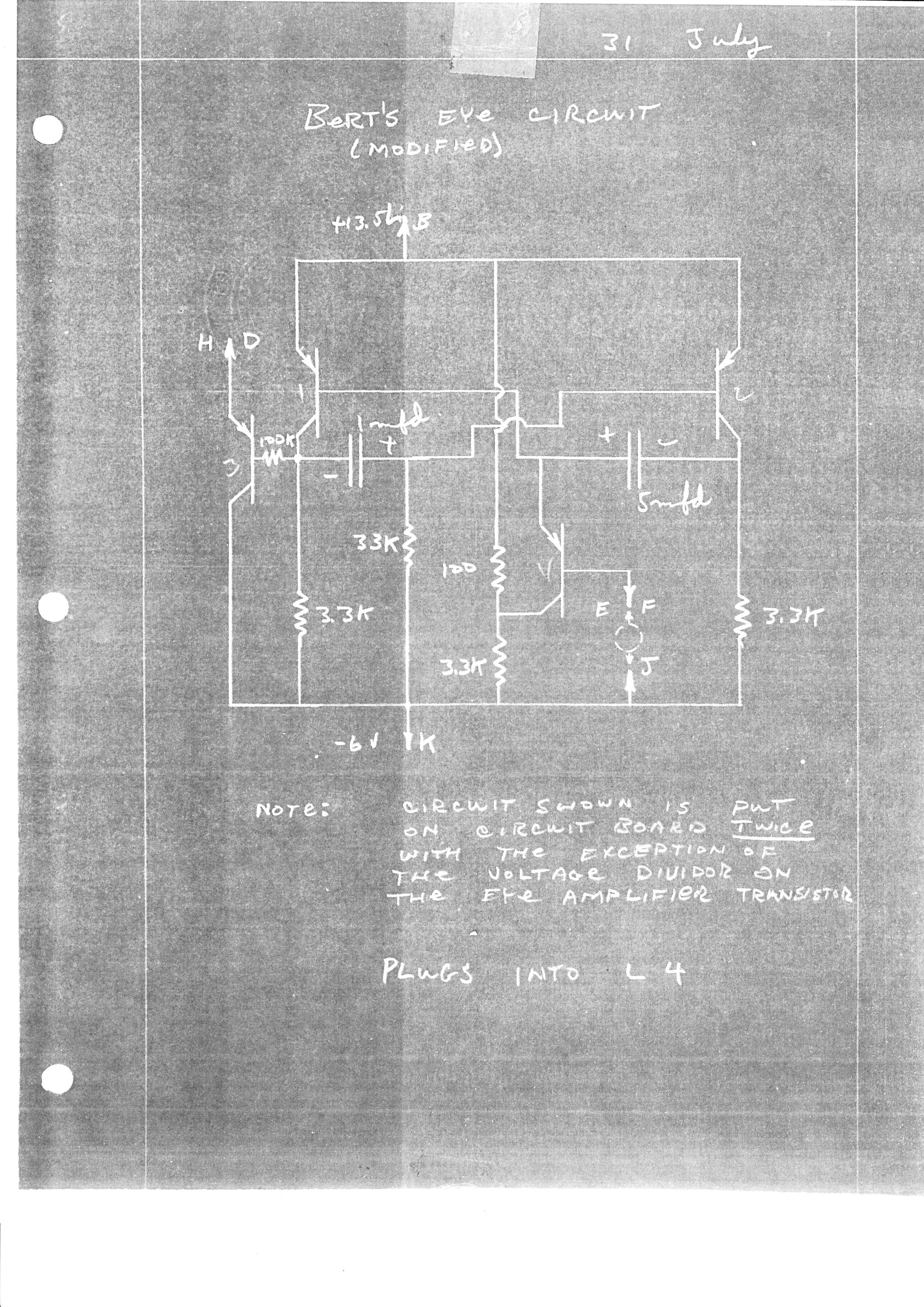
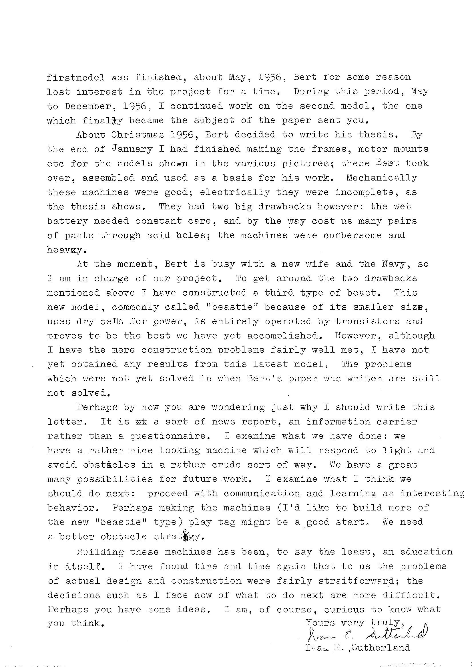
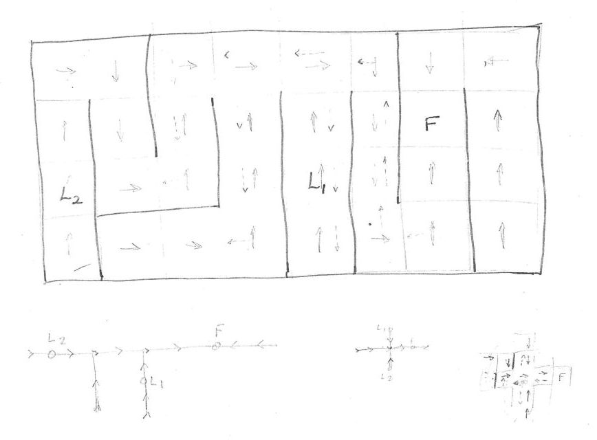
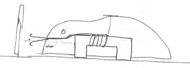
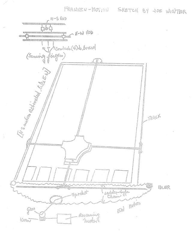
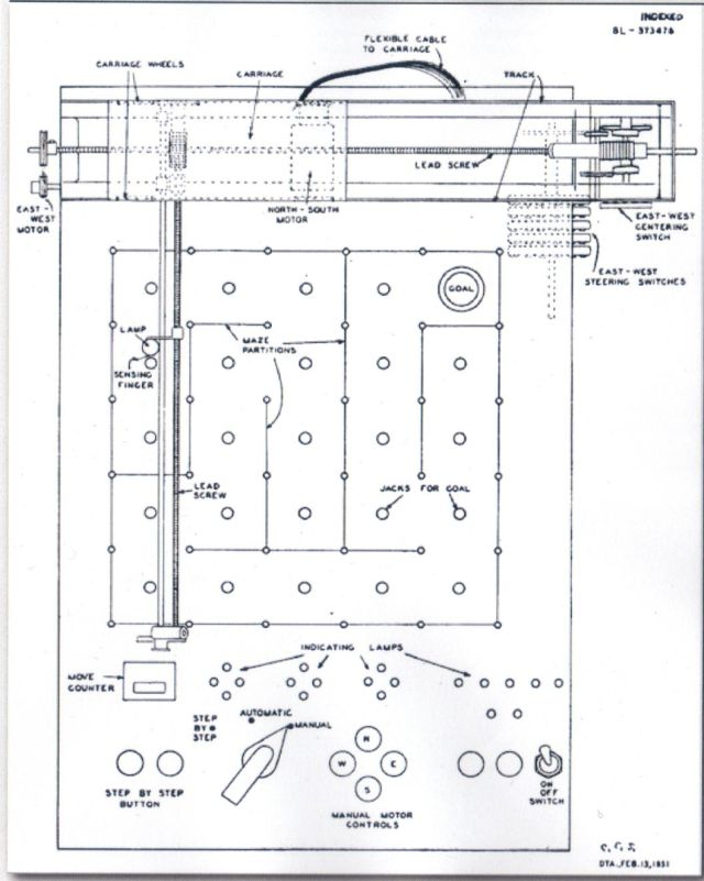
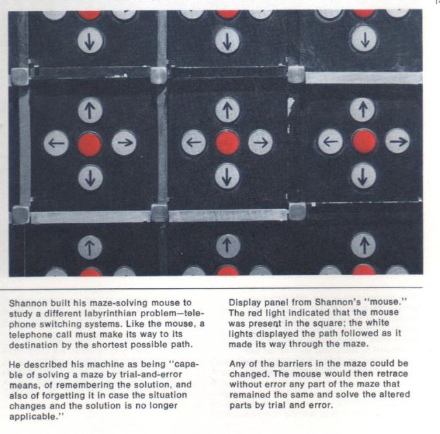
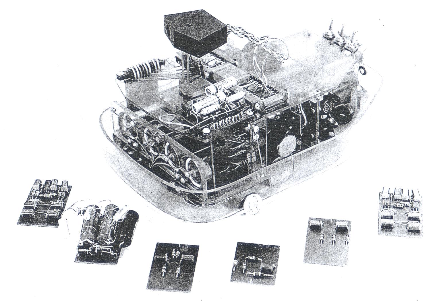
5. Franken (named after Frankenstein) is a maze-solving robot. The maze consists of an aluminum board with 32 squares, around which partitions may be set up in any desired pattern by a member of the audience so as to make a maze. The searching and moving element which explores the maze is a wooden mouse or rat containing a permanent magnet. This is moved by four electromagnets themselves moved by machinery underneath the aluminum surface of the maze. The computing unit consists of some 60 relays; the memory consists of a magnetic drum (called Magdum; see below).

When Franken is completed, a member of the audience will be able to go up to Franken, mark one square with "Food", another square with "Latch One" and another square with "Latch Two". The machine will then be able to learn successively that "Food" is in the "Food" square, and that it has to go to "Latch Two" first and then to "Latch One" so as to "unlock" the "Food" and satisfy its hunger. The machine will also learn the maze, discovering the path to each of the three special squares after exploration. The machine will not be able to distinguish a shortest path from the path which it first finds, but it willbe able to eliminate all blind alleys. Data: 75% complete; finish, laboratory style; reliability, not known; maintenance, will be difficult; our costs so far, about $4,000.

6. Magdum (from "magnetic drum") is a small magnetic drum (materials cost about $50) and associated circuits including some 60 electronic tubes, constructed in order to be the memory for Franken. It has one timing channel and one information channel, and at present can store 128 numbers of 2 binary digits. A member of the audience can select any one of the 126 registers, enter a two-binary-digit number (one of 00, 01, 10, or 11) and find some time later that that number is still there, seeing the number in two neon tubes. This machine was constructed by Ivan Sutherland, age 16, for science fair competitions; and from it he won a $3,000 scholarship to Carnegie Institute of Technology. Data: 99% complete; finish, professional style; reliability, about 97%; maintenance, difficult; our costs so far, about $1,500.


Tags: , , , , , , ,

1983 – “Six-Legged Hydraulic Walker” – Ivan Sutherland (American)

1983 "Trojan Cockroach", a Six-Legged Hydraulic Walker by Ivan Sutherland.

The Sutherland Walker was a six-legged all-terrain robotic designed by Sutherland Sproull Associates with the Robotics Institute at Carnegie Mellon University under contract to the Defense Advanced Research Projects Agency (DARPA). The robot used a gasoline motor to power its legs and required a driver to operate it via foot pedals. The machine would keep three legs on the ground at any given time, eliminating the need for balancing systems, though also limiting the speed of the system. Each leg could move forward, backwards, and side-to-side, allowing it to navigate across uneven surfaces.

walking.machine-02-x640

Image found at Adam Megacz images here.

marc-donner-sutherland-walker-x640

Marc Donner driving the walker "hands-free!"

See the complete Scientific American article pdf here.


From D. J. Todd's book "Walking Machines" (1985)

Sutherland's Hexapod
This machine, designed by I.E. Sutherland of Carnegie-Mellon University and Sutherland, Sproull and Associates, is significant in being the first man-carrying computer-controlled walking machine (Raibert and Sutherland 1983; Sutherland and Ullner 1984). Its design is also interesting for its use of a leg geometry and hydraulic circuit design intended to reduce the control burden on both computer and driver by automatically coordinating joint motions in ways suitable for walking.
The hexapod, whose basic geometry is shown in Figure 6.7, is about 2.5m long and the same width. It weighs about 800kg and is powered by a 13kW gasoline engine driving four variable displacement pumps. The walking speed in the alternating tripod gait is 0.1m/s. It can also walk sideways at rather more than half this speed.
It has an unconventional arrangement of its hip actuators. Two cylinders are mounted in a 'V' above the leg. It is possible to set the valves so that as one shortens the other lengthens in such a way as to produce horizontal movement, whereas if they both move in the same sense they move the leg vertically. (A third actuator for the knee produces sideways movement.) This hip arrangement is one instance of what Sutherland calls a 'passive hydraulic circuit'. Such circuits achieve joint coordination in two ways. First, actuators are sometimes connected together in series so that as oil flows out of one it must flow into the next. This forces the actuators to move the same amount. Second, if two or three are connected in parallel they will automatically share any applied load equally. In this connection their collective movement is actively controlled by a pump, but their differential movement determined only by the relative loading of the actuators.
The hip connection for horizontal movement consists of putting two actuators in series so that as oil flows out of the fixed end of one it flows into the fixed end of the other. The motion is exactly horizontal only if the plane of the cylinders is inclined at 45° (Sutherland and Ullner 1984). A series connection is also made between the front and back actuator-pairs on each side to coordinate their movement during the propulsion stroke. This arrangement is shown for one tripod-set of legs in Figure 6.8 [not shown-RH]. In this illustration legs 2, 3 and 6 are being driven together. Each side has a separate pump so only legs 2 and 6 are connected together; the coordination between this pair and leg 3 is achieved by non-hydraulic means. Other series connections are possible.
The parallel connection is used for various purposes such as raising and lowering a set of legs, and to connect the knee actuators. If the three knee cylinders of a supporting tripod-set of legs are connected in parallel then although their collective sideways movement can be controlled by a pump, their differential movement is free and compensates both for the movement of the knee in an arc during forward rectilinear walking and for the larger sideways knee movement which must occur during a turn. This knee coordination is perhaps the most successful application of a passive hydraulic circuit.
The valves are all directional, not proportional or servo, spool valves, which are relatively cheap and simple but cannot control speed. Speed is regulated by manual control of the displacement of the pumps. The combination of the main propulsion pump and sideways motion pump flow rates governs the speed and direction of walking and the rate of turn. The pump displacements are controlled by pedals and a joystick.
The role of the on-board computer is to switch the valves on and off in the sequence appropriate to the specified gait. It can interrogate joint angle and leg force sensors, and the driver's controls. Several types of program have been written to test different methods of control, and a special language (OWL) has been developed (Donner 1983). The robot, which was built as a way of learning about hydraulic actuation, has now been scrapped.


See other early Steam Men and Walking Machines here.


Tags: , , , , , , , , ,

1950 – Maze-Solving Mouse – Claude Shannon (American)

The diagrammatic view of the 1950-1 Maze-solving Mouse built by Claude A. Shannon.

Claude Shannon knew Edmund C. Berkeley quite well. Berkeley had two young associates working part-time with him on his early robots, by the names of Ivan and Bert Sutherland.  Ivan was soon to have Claude Shannon as his Thesis supervisor.  Berkeley was keen to add a maze-solver to his catalogue of small robots, and engaged the Sutherland brothers to build one. This was called "Franken" and will be subject to a later post. Shannon put together the two page document to assist Berkeley and the Sutherland brothers in their quest.

Although there are "indicating lamps" marked in the schematic, I cannot confirm that the above photo is of those indicators in that version of the maze-solving mouse.

I have not been able to confirm how many maze-solvers were built, both by Shannon and later copies by Bell Labs. We have a reasonable description of the 1951 model as it was presented to the Eighth Conference on Cybernetics. More information is available is on the later 1952  "Theseus" mouse model. See a later post on this, more well known version here.

The pdf of the 1951 paper titled "Presentation of a Maze-Solving Mouse" from the Eighth Conference on Cybernetics is available here ShannonsMaze51 .

Although the paper was presented in 1951, I believe this first version of Shannon's maze was built in 1950.

Tags: , , , , , , , ,

1957 – Machina Versatilis – Ivan Sutherland (American)

Ivan Sutherland with M. Versatilis.

Source: Carnegie Mellon University Archives

Machina Versatilis , pictured above and below, was so named due to the versatile modular plug-in boards. M. Versatilis was the final of three models built, and at least two of this model were supposedly built. The first version, see blog post here, was originally built in Spring 1956 by Ivan Sutherland's older brother Bert (William Robert Sutherland) and his then class room-mate Malcolm "Mac" G. Mugglin.

That model had shortcomings and was abandond. Later that year, Ivan took charge of the project and produced a second model. This model used a cast aluminium plate, easily removeable wet battery, and plastic bumpers. It still utilised vacuum tubes [valves] at this time. The third and final model was primarily built by Ivan in September 1957,  was fully transistorised and used only dry-cell batteries. 

To my knowledge, although Grey Walter had said he had built a transistorised tortoise in a letter dated Jan 1957, this is the first cybernetic animal to utilise transistors that we have proof of.

Another first was that a second M. Versatilis was built along with a light mounted on a rolling platform to be pushed around as a toy. Ivan later describes his idea on improving M. Versatilis even further with a direction-guiding gyroscope to enable a game of soccer to be played.  This effectively is the first ever mention of the concept now known as robo-soccer.

The pdf below, along with the letters published here give a good all round description of M. Versatilis.

There is a video clip featuring the Sutherland brothers giving a talk on their lives. There's a brief mention of the robots about 19 minutes into the clip titled "mom loved him best" https://www.youtube.com/sM1bNR4DmhU .

Electro-Mechanical-Animal Sutherland-  a pdf of the below article


Although thought to have been #6, the stamping clearly shows a '5', contradicting WGW's and Sutherland's correspondence.


Documents showing schematics of plug-in modules.

There are not many references to Machina Versatilis. Unfortunately one of the more recent tomes on the history of A.I. (Boden: Mind as Machine) incorrectly credits the Sutherlands' as the builders of Edmund C. Berkeley's "Squee" of 1951, rather than M. Versatilis.


See other Cybernetic Creatures here.

Tags: , , , , , , , , , , , ,

1956 – Mechanical Animal – William Robert “Bert” Sutherland / Ivan E. Sutherland – (American)

 This copy of a letter from 1957 describes the first "Mechanical Animal" built by the Sutherland brothers, Bert and Ivan.


Here’s a transcript of the letter sent from Ivan E. Sutherland to Grey Walter in 1957:

Nov 10. [IES  to WGW]
“Dear Sir:
Early last month I had sent to you two copies of a paper entitled “An Electro-mechanical Model of Simple Animals” which was submitted by my brother, Bert (William R. Sutherland), and his close friend, Mac (Malcolm G. Mugglin), to their department of Electrical Engineering. Perhaps a little of the history of that paper would be of interest to you.
I am now a Junior (3rd year) at Carnegie Tech, also studying electrical engineering – in this and many other things I have followed the lead of my brother. Bert is two years older than I, recently became married and is now on active duty as an officer of the U.S. Navy. Our interest in mechanical and electrical things probably comes from our father, a Civil Engineer from New Zealand: Ph. D. from London, but our first good luck and stimulation came when we met Edmund C. Berkeley in 1952.
Mr. Berkeley took an interest in the work that we had already done, namely a simple adding machine, and encouraged us to continue, both by suggesting problems and by providing funds for their solution. During the period October, 1952 to June, 1955 we worked under the guidance of Mr. Berkeley. We did a major protion [sic] of the work on a mechanical maze solving mouse similar to one constructed by Claude Shannon of Bell Labs. During the latter part of this same period, Bert left home for college, and I continued our work alone.
During this contact with Berkeley’s organization we often saw “squee”, his mechanical squirrel; this was our first contact with the species of mechanical animals. Our next contact came when we read your The Living Brain. We were both interested in all the things you have done, but most familiar with the mechanical and electrical aspects, and most interested in your Machina speculatrix. Can you imagine the joy of two young people reading about important work accomplished far away in a field they were just becoming part of?
It was no surprise to me when Bert suggested, about Christmas of 1955, that we build a mechanical animal also. On page 45 of Bert’s thesis is a picture of the first crude result. When this first model was finished, about May, 1956, Bert for some reason lost interest in the project for a time. During this period, May to December, 1956, I continued work on the second model, the one which finally became the subject of the paper sent [to] you.
About Christmas 1956, Bert decided to write his thesis. By the end of January I had finished making the frames, motor mounts etc for the models shown in the various pictures; these Bert took over, assembled and used as a basis for his work. Mechanically these machines were good; electrically they were incomplete, as the thesis shows. They had two big drawbacks however: the wet battery needed constant care, and by the way cost us many pairs of pants through acid holes; the machines were cumbersome and heavy.
At the moment, Bert is busy with his new wife and the Navy, so I am in charge of our project. To get around the two drawbacks mentioned I have constructed a third type of beast. This new model, commonly called “beastie” because of its smaller size, uses dry cells for power, is entirely operated by transistors and proves to be the best we have yet accomplished. However, although I have the mere construction problems fairly well met, I have not yet obtained any results from this latest model The problems which were not yet solved in when Bert’s paper was written are still not solved.
Perhaps by now you are wondering just why I should write this letter. It is a sort of news report, an information carrier rather than a questionnaire. I examine what we have done: we have a rather nice looking machine which will respond to light and avoid obstacles in a rather crude sort of way. We have a great many possibilities for future work. I examine what I think we should do next: proceed with communication and learning as interesting behaviour. Perhaps making the machines (I’d like to build more of the “beastie” type) play tag might be a good start. We need a better obstacle strategy.
Building these machines has been, to say the least, an education in itself. I have found time and time again that to us the problems of actual design and construction were fairly straightforward; the decisions such as I face now of what to do next are more difficult. Perhaps you have some ideas. I am, of course, curious to know what you think.”

CHALLENGE

I've tried to track down Bert Sutherland's thesis to obtain a picture and further details of this "beast", but without success. Maybe an American out there could find this information and I would happily publish it here. From the above article, the thesis was completed early 1957.