Posts Tagged ‘1959’

1959 – “DUHAB” – Lawrence Lipton / Bill Riola (American)

1959 – "DUHAB" (Detector of Undesirable HABitués) by Lawrence Lipton / Bill Riola.

duhab-1960-la-pic-library-1-x640

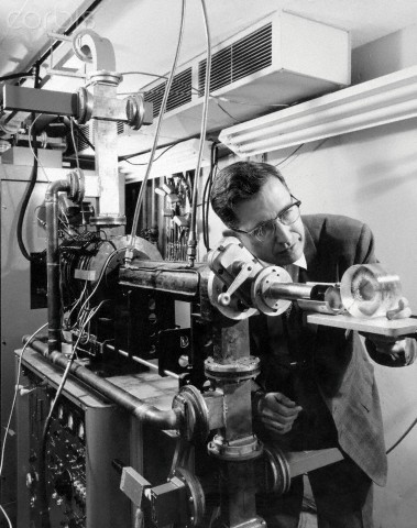
Photograph caption dated December 5, 1960 reads, "Electronic Cat Detects Subversives for Beatniks. Duhab accompanies poet-author Lawrence Lipton to weed out undesirables."
Image source: The Los Angeles Public Library.
Lawrence Lipton was talking to the Valley College Writer's Club.


beatnik-robot-65-x640
Source: The beatnik DUHAB robot

    Posted By: Scott Harrison | February 7, 2012

July 19, 1965: The original published caption reported:

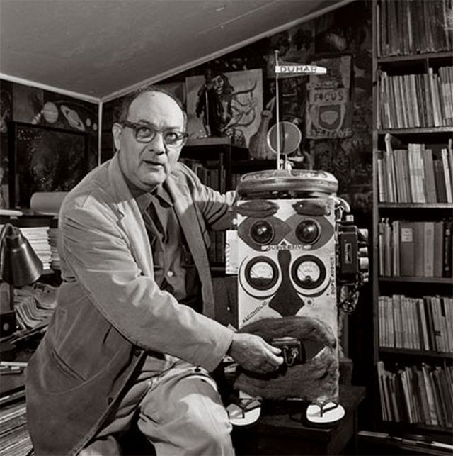
GADGET FOR TODAY–Author Lawrence Lipton, chronicler of the beatnik scene, demonstrates his “robot,” Duhab (Detector of Undesirable HABitués). Lipton says robot ferrets out the undesirables – including censors, book-burners.

By 1965, media outlets were reporting the beatnik era over. Not so, claimed Lipton, whose 1959 best seller, “The Holy Barbarians,” chronicled the Venice scene. As quoted in a Times article by staff writer Doug Mauldin, Lipton explained, “What happened is that the artistic element has gone underground. Artists, writers, painters and avant-garde filmmakers live and work in their own pads.”

“And there are two or three times as many true beats here as there were in the 1950s when they were getting all the publicity.”

But, as pointed out in Mauldin’s story:

He (Lipton) is particularly bitter about past campaigns to rid Venice of the Beatniks.

“The Venice West beat scene was the most promising attempt ever made to bring avant-garde culture to Southern California, and it was murdered by self-righteous, puritanical busy-bodies and hostile police,” he said.

The above portrait of Lipton accompanied Mauldin’s story in the July 29, 1965, Westside Edition of the Los Angeles Times.


lipton-riola-duhab-robot-Santa_Cruz_Sentinel_Oct_19_1959-x640


Source: Venice West: The Beat Generation in Southern California by John Arthur Maynard – 1991, p 123
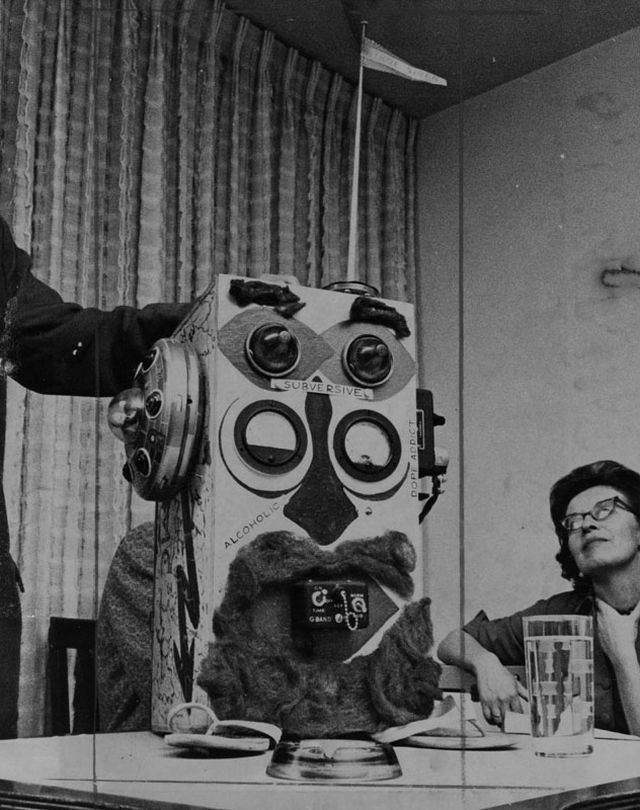
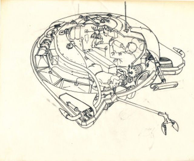
Larry Lipton, as "director of entertainment" for the Gas House, seemed torn between wanting to win and wanting to be right. Shortly after one of the police commissioners told him he had a responsibility to keep "undesirables" out of the Gas House, Lipton returned with an extraordinary contraption which he solemnly described as an "electronic doorman." Built to his specifications by the Gas House light crew and decorated by Bill Riola, it was a primitive but functioning robot with a little popeyed face, a built-in tape recorder, and an incredible array of sirens, whistles, bells, and flashing red lights. "Duhab"—short for "Detector of Undesirable Habitués"-was described as being able to sense the approach of "teenage werewolves, dope addicts, sex fiends, subversives, alcoholics, and homosexuals (male and female)," and members of the Venice Civic Union-in which event, all of its alarms were set to go off at once. Duhab made good theater, but bad hearing strategy; it helped make Lipton himself the issue, and gave the hearing examiner, Officer Thomas Mulhern, the opportunity to focus on the "moral character" of those who would be directing "the proposed entertainment."


Source: The Van Nuys News (Calif.), Sunday, Oct. 18, 1959   
Two-Week Delay Ordered in Venice 'Beatnik' Hearings
The West Venice "Beatniks" will have to wait two weeks before their request to have a City Police Commission examiner disqualified will be considered.
The commissioners refused Wednesday to discuss charges of prejudice against examiner Thomas Mulherin, who conducted hearings for an entertainment licence at a beatnik "culture center" known as the Gas House and located in West Venice.
Cries "Unfair!"
President John Ferraro said the disqualification charges will not he discussed until all commissioners have had a chance to study the transcript, which includes more than 1000 pages of testimony.
Atty. A. L. Wirin, representing Atty. Al Matthews, owner of the Gas House, told the commission that he was being treated unfairly and that he had been told the matter would be on Wednesday's agenda.
Ferraro speculated that it would be two weeks before the commissioners will he prepared to discuss the matter.
In a brief filed last week, Wirin accused Mulherin of "unfair and prejudicial conduct" in conducting hearings on an application for an entertainment permit at the Gas House, 1540 Ocean Front Walk.
Wirin, accompanied by Matthews and beatnik author Lawrence Lipton, was not permitted to discuss the matter at all at Wednesday's session.
Complaint Detailed
Before the session, Wirin said he would base his arguments on three main points brought out by earlier hearings in which he claims Mulherin showed "prejudice and bias" against the beatniks. They are:
1—That Mulherin said he doubted whether Lawrence Lipton, author of "The Holy Barbarians," knew the meaning of the word "moral."
2—That Mulherin said he doubted—after reading Lipton's book—that Lipton was a responsible person to manage entertainment at the Gas House.
3—That Mulherin accused Lipton of injecting the racial issue into the hearings when, Wirin said, it was the commission's representative who injected it into the hearings prior to Lipton's testimony.
Wirin said he will cite numerous items in the transcript of earlier hearings to support his motion to disqualify Mulherin.
Have Poetic Robot
The newly-formed defense committee for Culture in Venice, headed by Robert Chatter-on, announced that several mass meetings will be held to raise money for the entertainment license fight. At these meetings, typical Gas House entertainment programs will be offered, it was stated.
One of the meetings will be held in the Gas House, but a beatnik robot—that writes and recites poetry with music—will be used.
"The idea." Chatterton explained, "is that a robot does not rate as 'live entertainment,' which the police have banned at the Gas House, pending the license hearings.
Names New Device
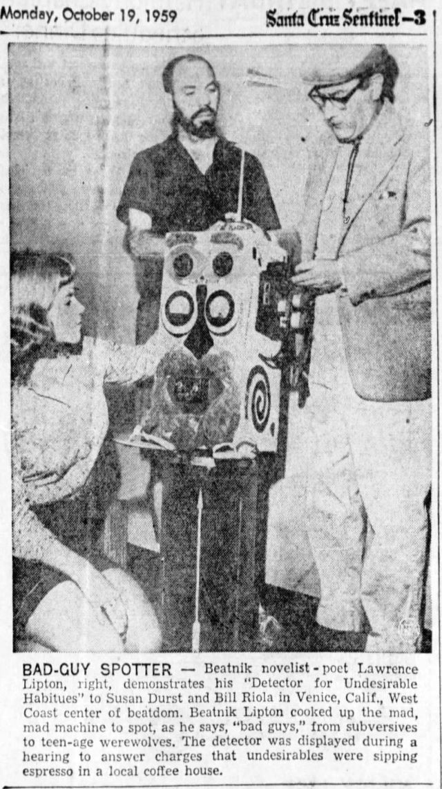
The beatniks promised to bring to this afternoon's hearing the bearded and sandaled Duhab, the electronic robot "detector of undesirable habitués," which Lipton said is capable of "screening out alcoholics, dope fiends, teenage werewolves and other undesirables at the door, thus evading the wrath of the Venice Civic Union.
"A new detection device has been added since Duhab was unveiled last week," Lipton added.
"It is a set of heavenly chimes that sound on the appearance at the Gas House door of any member of the Civic Union."


See the full list of Fake and Pseudo Automatons and Robots here.


Tags: , , , , , , , , , ,

1959 – SP-350 Denise Diving Saucer – Jacques-Yves Cousteau et al (French)

????????????????????????????????????????????????????????????????????????????????????????????????????????????????????????????????????????????????????????????

The SP-350 Denise, famous as the "Diving saucer" (Soucoupe plongeante), is a small submarine designed to hold two people, and is capable of exploring depths of up to 400 metres (1,300 ft). It was invented by Jacques-Yves Cousteau and engineer Jean Mollard at the French Centre for Undersea Research. It was built in the year 1959 and usually operated from Cousteau's ship, the Calypso.

An electrically operated manipulator arm can be fitted at the front of the craft so that objects can be picked up and examined through the portholes.

soucoupe-denise-by-jean-charles-roux-x640

MANIPULATORS: One mounter port side forward, hydraulically driven, with two degrees of freedom (shoulder / hand). Basically this is a pivoted arm (rotating in one plane) which folds under the brow when not in use and is extended downward in the vertical to grasp. The vehicle itself can be manoeuvred to attain somewhat greater arm versatility.

cousteau-clamshell-manip-x640

SP-350 diving saucer-x640

clam-arm-denise-cousteau-pic-harold-edgerton-x640

Photo by Harold Edgerton.

cousteau-saucer-65--x640 

 Jacques-Yves Cousteau with his Diving Saucer Denise.

Photo de Rémy BOISSET-x640

soucoupe-denise--x640


sp800-roux-x640

The later SP800 showing a similar "clamshell" arm. Image by J.C. Roux. Source: here.

soucoupe-sp1200-by-jean-charles-roux-x640

The later SP1200 showing a similar "clamshell" arm. Image by J.C. Roux. Source: here.


cousteau-saucer-pat-1-x640

Self-propelled submersible vessel

Publication number    US3103195 A
Publication type    Grant
Publication date    Sep 10, 1963
Filing date    Jul 12, 1960
Priority date    Jul 22, 1959
Also published as    DE1866612U
Inventors    Laban Andre, Gagnan Emile, Mollard Jean, Cousteau Jacques-Yves
Original Assignee    Spirotechnique

The original French patent No. is FR1241757A.


See other early Underwater Robots here.


1959 – Lunar Construction Vehicle from Project HORIZON – U.S. Army (American)

ProjHorizon-59-SaLunarConstructionVehicle-x640

Lunar Construction Vehicle with manipulator arms.

1974Thenext50yearsonthemoon21-x640

Above image from “The Next 50 Years on the Moon”, 1974.

NASA Study Summary: “Project Horizon, Vol 2, Technical Considerations and Plans”

Here’s a big study from 1959, done by the US Army, right about the time NASA was just becoming a going concern. There was a lot of interservice and interagency rivalry at the time with the AF and Army and Navy vying for the opportunity to dominate the space field– a field which Eisenhower SPECIFICALLY wanted the military excluded from to the extent possible… hence the creation of the civilian NASA in late 1958.

Here’s Project Horizon, the US Army’s plan to build a 12 man moonbase by 1965-66. The plan calls for the use of the ABMA’s Saturn booster (Saturn I) with an upgraded “Saturn II” to follow, using upgraded “H-2” engines (seriously upgraded H-1 engines from Saturn I). Project Horizon would also leverage existing technology by using the Titan I first stage as a second stage, and the Centaur, which was starting development by this time, as a third stage, with plans for an enlarged Centaur for the second and third stages of Saturn II and a smaller Centaur-based fourth stage for both rockets. It also planned to develop in-space refueling (what was later called “Earth Orbit Rendezvous” for the lunar mission, using several Saturn I and Saturn II launches to lift the fuel and equipment to orbit… which this report coming out of ABMA, which employed Von Braun and his team as the stars at the time, it only makes sense that this report closely mirrors Von Braun and Co.’s ideas about how to do a moon mission once Kennedy gave it the nod, though Houbolt proved that Lunar Orbit Rendezvous was the only way to do it within the decade target Kennedy set). The report even talks about the possibility of an 8 F-1 engined super booster that would later become known as NOVA. There’s also information about nuclear upper stages, which would supplement the Saturn I and Saturn II and F-1 superbooster and could end up landing as much as 420,000 lbs of cargo on the moon! There’s also a 2001 ring-like space station to serve as refuelling point for outbound lunar rockets, and several different lunar landers, all of which would use liquid hydrogen descent propulsion coupled with hypergolic ascent propulsion, later hopefully replaced with hydrogen ascent propulsion to improve performance. Even the idea of nuclear landers is thrown around…

A new equatorial launch center was to be built, most likely either on Christmas Island in the mid-Pacific, 2 degrees north of the equator, or on the Brazilian coast, 2 degrees south of the equator. The flightrate of Saturns to support the program was estimated at 5.3 launches PER MONTH! (ambitious, weren’t they!) Also, there were plans for two new space centers, one to do research on the basic problems of the designing the vehicles and their payloads and systems, the other having two facilities designed specifically to address the human factors and astronaut training and simulate the lunar and space environment. Basically this is the genesis of the idea for what became the Marshall Space Flight Center after the ABMA and it’s team and facilities were handed over to NASA from the Army by Eisenhower, to do the research into building the rockets and the systems to support them, and the astronaut training facility and human program research center (along with mission control) which later became the Johnson Space Center in Houston.

Source: Luke Strawwalker


See other early Space Teleoperators here.

See other early Lunar and Space Robots here.


Tags: , , , , , , ,

1959-61 – Concept O-9 Manned Utility Tug – (American)

Concept O-9: Rendezvous by Manned Utility Tug

From a report compiled between 1959-61 and presented in 1961 are various concepts {Suffixed by 'O' for Orbital Rendezvous). This extract only selects those concepts that have a manipulator component.

WADD TECHNICAL REPORT 60-857
LAUNCHING AND ALIGHTMENT SYSTEMS FOR AERO-SPACE VEHICLES
Nelson T. Levings, Jr.
Cleveland Pneumatic Industries, Inc.
May 1961
Flight Dynamics Laboratory
Contract No. AF33(616)-6572
Project No. 1369
Task No. 13529
Wright Air Development Division
Air Research and Development Command
United States Air Force
Wright-Patterson Air Force Base, Ohio

FOREWORD
The work described in this report was accomplished by the Instrumentation and Control Division of Cleveland Pneumatic Industries, Inc., under Contract No. AF 33(616)-6572, Project No. 1369, entitled, "Launching and Alightment Systems for Aero-Space Vehicles, Task No. 13529.
This project was administered under the direction of the Flight Dynamics Laboratory, Directorate of Advanced Systems Technology, Wright Air Development Division [WADD], with Mr. Wallace Buzzard as Military Project Engineer, having superseded Lt. Don Austin in January 1960.
This report covers work conducted from June 1959 to January 1961.
Mr. Nelson T. Levings, Jr., was Contractor Project Engineer, assisted by specialized engineering personnel from each Division of Cleveland Pneumatic Industries, Inc.

CONTENTS

…………

30 Concept O-1: Attachment by Tail Hook Snag 62
31 Concept O-2: Attachment by Self-Guiding Probe Through Hoop 63
32 Concepts O-3 and O-4: Shock Mitigation between Two (2) Axially Aligned Vehicles 64
33 Arresting Gear for Storing Impact Energy for Subsequent Ejection Departure – Concepts 0-3 and 0-4 65
34 Concept O-5- Remotely Controlled Magnetic Contactor on Freely Swinging Cable 66

35 Concept O-6: Rendezvous by Utility Tug – Remotely Controlled 67
36 Concept O-7: Attachment by Mechanical Grappling Hook – Close Range 68
37 Thrust Compensator and Line Control for Concept 0-7 69
38 Concept O-8: Orbital Attachment by Self-Guiding Probe 70
39 Concept O-9: Rendezvous by Manned Utility Tug {See top for illustration] 71
40 Concept O-10: Rendezvous by Simple, Remotely Controlled Tug 72
41 Concept O-11: Long Range Attachment by Probe and Drogue – Heat or Light Sensitive 73
42 Latch Coupling for Concept 0-11 74
43 Mechanical Magnetic Ring Coupling for Concept 0-11 75
44 Concept O-12: Rendezvous of Axially Aligned Vehicles by Penetration 76
45 Concept O-13: Rendezvous by Surface Contact 77


46 Concept O-14: Rendezvous in Matched Orbits by Man in Environmental Suit 78


47 Concept O-15: Attachment by Mechanical Parallelogram Grappler 79


48 Concept O-16: Attachment by Gas Actuated Parallelogram Grappler 80

………..
2.3 ORBITAL RENDEZVOUS
Work during this phase of the project was faced with many unknowns. Initially, a cursory study was made in the area of orbital mechanics to determine what precision was required from thrust control during orbital rendezvous and if there might be a mass trade-off between shock mitigation and thrust control equipment. Again, airframe manufacturers and other agencies contributed to this effort.
The findings are summarized below:
a. The planes of the orbits of the target and intercept vehicles must be within minutes of arc.
b. The orbits must be matched in shape, size, and orientation within minutes of arc and, at time and point of rendezvous, the vehicles come together within close proximity.
c. The vehicles must be closely "in phase'" to affect rendezvous.
d. The vehicles, in the case of earth orbit rendezvous, should avoid lengthy exposure to the lower Van Allen radiation belt.
e. To make a rendezvous possible, corrective vernier rockets will have to operate within extremely precise limitations of thrust and cut-off times to bring relative velocity within acceptable limits.
f.* It was determined that, if each vehicle's velocity vector does not intercept the other's center of gravity on rendezvous, there may be a tumbling problem after contact.
To hold the mass of the shock mitigation equipment to an acceptable percentage of total mass, relative velocities were not to be considered over 35 ft/sec.
Parameters forming the framework for orbital attachment concepts include the same values applied ia-paragraph 2. 1; therefore:
a. 4 "earth" g's max. safe deceleration.
b. 1.5 safety factor applied to deceleration.
c. Vehicle gross weight approximately 20 tons (earth weight).
2.4 EARTH MANEUVERS
In this area, many concepts were submitted. However, since the problem of return to earth and landing are under detailed study in the Air Force as a portion of the Dyna-Soar development, no attempt was made to list a framework for concept formulation concerned with earth maneuvers.
* Any gravitational attraction between two bodies can be discounted with regard to bringing or holding them together. Eg: it takes only 2 (10)-5 radians/sec. rotation about a common C.G. to make two bodies of 100 tons each (whose C.G. 's are 100 feet apart)to balance the gravitational force holding them together.
3. SCOPE OF CONCEPTS
As the project progressed, the concepts submitted were categorized as to earth allghtment or departure, (labeled E-1, E-2, etc.), orbital attachment (0-1. 0-2, etc.), and lunar alightment or departure (L-l, L-2, etc.). They were sub-categorized as logically as possible, as to their nature — mechanical, electro-mechanical, multi-strut, etc.
5. 1 CONCEPTS SUBMITTED
The appendix shows the concepts submitted in pictorial form. They are separated into the three major categories shown above. Class I illustrates earth alightment and departure, Class II orbital rendezvous, and Class III lunar alightment and departure.
The sixteen (16) [only 6  Orbitals] most promising concepts as selected by WADD, are listed below:
Class I – Earth Concepts
……..
Class II – Orbital
3. O-1 Attachment by tail-hook snag.
4. O-2 Attachment by self-guiding probe through hoop.
5. O-7 Attachment by mechanical grappling hook — close range,
6. O-8 Orbital attachment by self-guiding probe,
7. O-11 Long-range attachment by probe and drogue — heat or light sensitive,
8. O-15 Attachment by mechanical parallelogram grappler. [This is the only illustrated concept shown here that made it through.]

Class III – Lunar Concepts
……..
NOTE: The 34 concepts eliminated from further study by WADD were rejected on the basis of (a) insufficient anticipated reliability, (b) lack of
confidence In state-of-the-art advances in that area and, (c) in the case of bags, balloons, and parachutes, cognizance by other WADD Laboratories.

Contributing Agencies:

1. Brunswick Corporation, Muskegon, Michigan
2. Cleveland Pneumatic Industries, Inc., All Divisions
3. Convair Astronautics Division, General Dynamics Corporation,San Diego, California
4. E. I. DuPont de Nemours & Company, Wilmington, Delaware
5. General Electric Company, Philadelphia, Pennsylvania
6. Goodyear Tire and Rubber Company, Akron, Ohio
7. Human Sciences Research, Incorporated, Arlington, Virginia
8. International Telephone and Telegraph Corporation, South Bend, Indiana
9. Jet Propulsion Laboratories, Pasadena, California
10. Lockheed Aircraft Corporation, Los Angeles, California
11. Lockheed Aircraft Corporation, Sunnyvale, California
12. National Aeronautics and Space Administration, Washington, D. C.
13. North American Aviation Corporation Missile Division, Downey, California
[No 14 in document]
15. North American Aviation Corporation, Los Angeles, California
16. Republic Aviation Corporation, Farmingdale L.I., New York
17. Wright Air Development Division, Wright-Patterson Air Force Base, Ohio
18. Dr. Waldo Kliever, Instrumentation Physicist, Cleveland, Ohio
19. Dr. Fred S. Singer, Radiation Physicist, University of Maryland

Document sourced from here.


See other early Teleoperators here.

See other early Lunar and Space Robots here.


1962 – Unmanned Space Mobot (Concept) – Hughes Aircraft (American)

Hughes Space Mobot concept.

John W. Clark, Ph.D.
NUCLEAR ELECTRONICS LABORATORY
HUGHES AIRCRAFT COMPANY
CULVER CITY, CALIFORNIA
ROLE OF REMOTE HANDLING IN SPACE [c1962]
Orbiting Vehicles
In connection with orbiting vehicles, remote-handling techniques can advantageously be
employed in connection with maintenance and repair, assembly in orbit, and personnel transfer.
Maintenance and repair is, of cause, confined to orbiting vehicles so expensive as to justify the cost of orbiting a repair system rather than orbiting a complete new satellite.
Assembly of large orbiting vehicles may advantageously be accomplished by remote-control techniques. These techniques will permit the assembly of vehicles far too large to orbit in a single payload. Control of the assembly system may be accomplished either from a ground station or from a manned orbiting vehicle.
Personnel transter, as, for example, between a re-entry vehicle and a manned space station may be facilitated by those of remote-control techniques in accomplishing the final contact between the two space vehicles and to accomplishing an airtight closure or junction between these two which will be safe for personnel transfer.
Lunar Applications
Remote-control techniques will find many applications in the exploration and development of the lunar surface for scientific and military purposes. Preliminary operatiins will probably be accomplished by systems committed from the earth. This maybe followed by development of luna sites, also by earth-controlled vehicles.
After the development of lunar sites, manned lunar expeditions may become feasible. Such expeditions will benefit from the availability of sophisticated remote-handling vehicles which can, under control of the pilot of the space ship, accomplish lunar exploration or advance the development of the sites prepared by the earth-controlled Mobots.
Finally, after habitable lunar stations become available, operations of all kinds upon the lunar surface will still be in large part carried out by Mobots under control of the inhabitants of the lunar station.

DESIGN OF REMOTE-HANDLING SYSTEMS FOR SPACE
This discussion excludes consideration of lunar Mobots. It is, of necessity, confined to certain of the problems uniquely applicable to remote handling in connection with orbiting space vehicles.
Vision
The meet important of the senses, vision, requires particular consideration under space conditions. The harsh illumination will require unusual control of the TV cameras, and also may require specially conrolled illuminations an aid to working on the shadowed side of orbiting objects. The lack of background and of vertical reference are serious psychological problems. Consideration may well be given to artificially inserting both background and vertical reference within thee TV system so that the operator's TV monitors present him information similar to that to which he is accustomed.
These requirements are superimposed upon those applicable to any remote-handling system. Sufficient experience has now been gained with operation of Hughes Mobots to make one confident that adequate vision for performing complex or precise tasks can be furnished to a trained operator by the appropriate use of two or more conventional TV cameras. Additional quantitative studies concerning the relative utilily of multi-camera, stereo, and other methods of vision, with specific reference to the conditions existing in space, will be most valuable.
Dynamics of a Gravity-Free Environment
Operations under orbiting conditions present a novel situation since on is  concerned with acceleration rather than velocities and a relatively small system of limited power consumption can direct the motions of quite heavy objects if appropriate consideration is given to their inertia. For example, an arm capable of lifting an earth weight of 40 pounds can impart a useful acceleration to much heavier masses under weightless conditions. This arm can move a 500-pound mass 5 feet in 2.8 seconds in an optimal situation in which a mass is accelerated for one-half the time and decelerated for one-half the time. Clearly, spacial operator training will be required to obtain successful performance under these conditions, so different from those to which we are accustomed.
Command and Data Link
In cases in which control is provided from a manned space craft, the command and data link can be transmitted from controlling  vessel to Mobot via cable. The time division multiplex command system utilizing trinary digital coding is particularly suitable since it requires only two conductors in the cable. This system has been described in detail in an article by Don A. Campbell (ref. 1). Situations in which radio command is required are also well handled by this same system, which minimizes bandwidth required of the communication channel. The data link which conveys vision, sensory, and other analog information from Mobot to command station can employ the same cable as does the command link. In radio-controlled systems a separate data link is required. The detailed considerations, primarily the trade-offs between power and bandwidth, are different in each case. Particular attention must be paid to utilizing TV systems in which minimum video bandwidth is required in comparison with the conventional RTCA• standard system which is quite wasteful of bandwidth.
Arm Geometry
Numerous space applications are best handled by specific mechanisms tailored to perform specific tasks. No general comments can be made about such mechanisms. There is, however, a definite need for general-purpose handling mechanisms. To meet this need, the Hughes Mark 2 Arm has been developed (figure 1). Its three articulations are each capable of +-90deg motion in either plane. The tong rotates continuously. Its parallel jaws open to a 4-inch width or close completely. They will rotate continuously in either direction. This arm is completely self-contained. All actuators and other mechanisms are included within the arm structure. The only auxiliary space required is that occupied bt the command system. This arm is not presented as the ultimate arm design, but is presented as indicative of a general-purpose arm capable of handling a wide variety of manipulative requirements in the presence of obstacles or in cramped quarters.
•    Radio Technical Committee for Aeronautics
Locomotion
In connection with satellite and orbital vehicle handling arms, only two methods of locomotion appear feabible. These are rockets or jets for traversing the space between one orbiting object and another, and auxiliary arms for moving about on or in a large orbiting vehicle. The preliminary sketches of space Mobots (figures 2 and 3[7]) indicate a four-armed Mobot based on this concept. In general, two of its arms are employed for moving it about in connection with its operations on a orbiting vehicle, while the other two are free for performing any manipulations required.
The Space Environment
The space environment (high vacuum, extremes of temperature, zero gravity, etc.) will have controlling influence to the detailed design of the components which make up any space Mobot. Fortunately, adequate design information is becoming available upon which one can base such engineering design. Further environmental test facilities are becoming available in which components or complete systems can be tested to insure their performance in the space environment.
SUMMARY
Concepts
The above discussions of the role of remote handling in space leads to the preliminary concepts shown in figures 2 and 3[7]. These Mobots employ jets or rockets to move about in space. They are furnished with four ams and two "eyes." The four arms, which are identical, can be utilized for moving the Mobot about on the vehicle on which it is working, positioning it during performance of the task, or guiding or manipulating the objects handled. Even a relatively small Mobot, such as those in figures 2 and 3[7], can handle quite  heavy objects in space if the operator is properly trained in the dynamics of space operations as outlined in the above discussion of the gravity-free environment.
These Mobots may be controlled by cable from a manned space ship or from a ground station by radio beams. In the latter case, it may be necessary to utilize orbiting vehicles as relay points for control of Mobots which do not stay within the visual horizon of any one ground station.
CONCLUSIONS
The work performed to date at Hughes on the electronically controlled remote-control systems to perform complex operations has demonstrated the feasibility of this method of accomplishing useful work an a hazardous environment. Work now in progress demonstrates the feasibility of designing mechanical and electronic structures which will perform in a satisfactory manner in the environmental conditions which prevail in space. Space MOBOTS are technically feasible and can be engineered economically and effectively to accomplish any given tasks which may be placed upon them by our Space program,
REFERENCE
1. Campbell, D. A., "Multiplex Circuits for Control of a Robot," Electronics, 22 January 1960.


From 1960, Ray Goertz, who invented electrically remote manipulators for the nuclear industry, together with his team at Argonne Nuclear Laboratories (ANL), were engaged by NASA to specify teleoperator configurations for the Lunar space program. The result is illustrated above.

It should be noted that floating vehicles share one problem. This is their inability to stay immobile relative to the object on which they must act. Hence, they are equipped with docking arms, other than the manipulator(s) directly intended to execute the task, to attach them to the object of their task, whether this is another satellite or an underwater oil platform.


Most of the Hughes Aircraft Mobot concepts were based around the Mobot Mk II arm.

Mobot Gripper specification.


Dr. John W. Clark, Manager of the Nuclear Electronics Laboratory at Hughes Aircraft Corporation, headed the Mobot group.


See other early Teleoperators here.

See other early Lunar and Space Robots here.


Tags: , , , , , , , ,