Posts Tagged ‘Space Pod’

1954 – “Bottle Suit” – Wernher von Braun / Walt Disney (American)

"Bottle Suit"

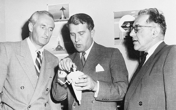
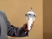
Wernher von Braun holding model of the Bottle Suit.
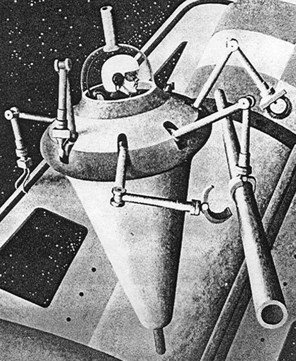
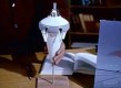
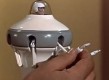
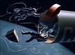
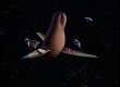
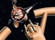
Bottle Suit

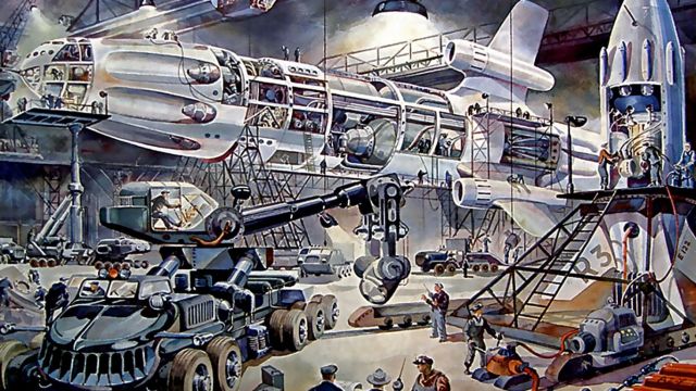
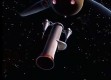
The Bottle Suit shows that when you plan to make your dreams come true, you have to create a number of intermediate solutions to problems you didn't anticipate. Problems like how to assemble a Space Station in Space. In order to assemble his proposed space station Von Braun designed a new, one man type of spaceship, a spacesuit.  The Bottle suit evolved as part personal spaceship and part Swiss Army Knife.

This was probably the first space suit von Braun had designed specifically with the idea of allowing a single person extended duration in space.  It would be used to assemble, not only the space station, but all the additional ships needed for his proposed Moon and Mars expeditions.

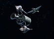
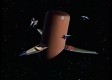
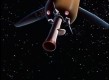
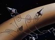
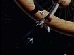
A versatile suit for construction, it was Gyro stabilized and had seven arms with different tools attached to each arm for the operator to use.  Because you cannot put tools “down” when working in space you better always have them attached to you to prevent them from floating away. And because of that, the Bottle suit was well equipped for construction jobs in space.       .

Also interesting is that it had rocket propulsion both at the top of the suit and below the suit to ensure it could both accelerate and decelerate. However, I have found no indication that it had any yaw or pitch thrusters to control its movement in those directions. Therefore it must have been using gyroscopes internally for rotating in these axes.  This is an important pioneering development of a truly radical concept that would allow humans to work in space. Source: RogersRocketships.

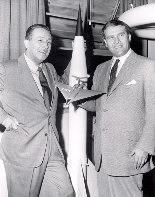
Walt Disney with Wernher von Braun.

Selected von Braun text from the 1955 Walt Disney film, Trip around the Moon.

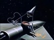
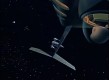
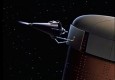
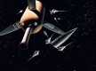
".. For the difficult job of re-assembling the structure [space station] we have provided a new type of space suit. Using gyros and two small rocket motors the operator can tilt and move in any direction. Located outside would be seven remotely controlled mechanical arms, each a speacilized tool. By rotating himself within the space suit, the operator can use any of the arms of the variety of tasks in ass,embling the space station. …"

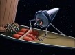
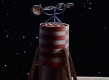
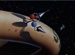
"… Two crew members make their way to the cargo ship. First the motor and tanks are detached. Then two bottle-type construction suits are removed from the hull. When fitted in the air-lock, each of these construction suits will receive an operator. …"

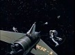
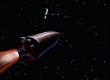
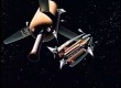
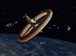
"The sections of the cargo ship are moved back to make way for other supply rockets soon to arrive."

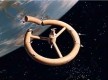
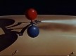
"Construction of the space wheel now begins…The sides of the cargo .. are mechanically separated.  Built-in tanks compressed air inflate the inner section of the hub..

Thin metal plates are immediately placed over the thin plastic … outside to protect it from meteorites …The first workday in space draws to a close."

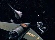
"Every 24-hours another cargo rocket will arrive in orbit. and the air-lock it attached .. to the sub-section and used as temporary quarters for eating and sleeping.

..can be assembled in the correct order.."


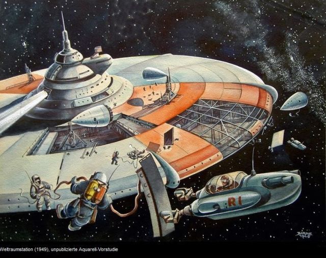
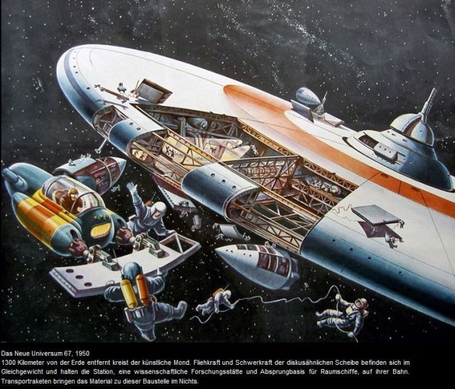
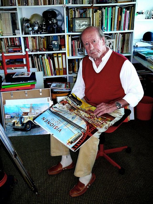
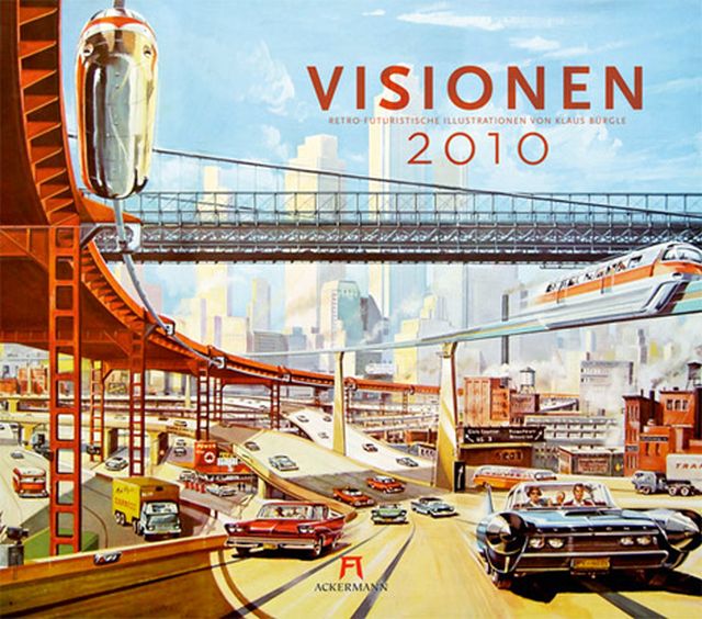
Note: The concept of a man inside a space capsule using manipulator arms largely came into being as a result of the logistics of getting man to the moon and beyond. The Space Station idea was conceived by Konstantin Tsiolkovsky in the early 20th century and then by Hermann Oberth about two decades later. In 1929 Herman Potočnik's The Problem of Space Travel was published, the first to envision a "rotating wheel" space station to create artificial gravity. But how to build a space station? Wernher von Braun was possibly, and probably the first to fully articulate the concept. When Walt Disney wanted to make his Space films (1954), von Braun was his consultant, and von Braun's ideas were visualised in the form of a "bottle suit".  Von Braun was thinking about space stations in 1952, possibly earlier. I have not read or heard of Tsiolkovsky, Oberth or Potočnik mentioning space tugs or the like.  The earliest idea I've found to date is the illustrator Klaus Bugle, who, in 1949, produced some illustrations on space station construction and showed space tugs with manipulator arms. Was he illustrating von Braun's ideas, or are these his own? For all intents and purposes, von Braun can be considered the grandfather of Space Station design and construction.

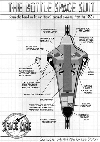
Image by Lee Staton.


Gallery of images found on the web.

Invalid Displayed Gallery


See other early Space Teleoperators here.

See other early Lunar and Space Robots here.


Tags: , , , , , , , , , ,

1949 – Space Tug (Illustration) – Klaus Bürgle (German)

Space Tug – 1949

The above image from a 2010 calendar with Bürgle's illustrations. I don't know if the Space Station illustration was previously published and if so, where? The caption suggests it was unpublished at the time.

The Space Tugs are being used to hold and manoeuvre large panels during construction.

Klaus Bürgle – Image by Tommy Laeng.

The graphic artist Klaus Bürgle created in the fifties and sixties of the last century a rich imagery of the future. The exploration of space was certainly his favorite subject, but many of his images also show futuristic cities and transportation.

Bürgle was born in 1926 in Stuttgart, where he attended from 1948 to 1951, the State Academy of Fine Arts. He was educated by professors Rössing and Schneider. After a year working in a graphic studio he became independent in 1953.

His technical interests soon meant that Bürgle is specialized in technical and scientific subjects and created for a variety of popular science books and magazines cover images and interior illustrations. He also worked for scientific television series.

Bürgle's 2010 Calendar cover.


Notes: The concept of a man inside a space capsule using manipulator arms largely came into being as a result of the logistics of getting man to the moon and beyond. The Space Station idea was conceived by Konstantin Tsiolkovsky in the early 20th century and then by Hermann Oberth about two decades later. In 1929 Herman Potočnik's The Problem of Space Travel was published, the first to envision a "rotating wheel" space station to create artificial gravity. But how to build a space station? Wernher von Braun was possibly, and probably the first to fully articulate the approach. When Walt Disney wanted to make his Space films (1954), von Braun was his consultant, and von Braun's ideas on construction were visualised in the form of a "bottle suit" with arms.  Von Braun was thinking about space stations in 1952, possibly earlier. I have not read or heard of Tsiolkovsky, Oberth or Potočnik mentioning space tugs or the like.  The earliest idea I've found to date is the illustrator Klaus Bugle, who, in 1949, produced some illustrations on space station construction and showed space tugs with manipulator arms. Was he illustrating von Braun's ideas, or are these his own?


More Bürgle illustrations of interest.

A depiction of unmanned moon crawlers originally for the Surveyor program. The crawler on the right-hand side is actually the Sperry luna crawler.

Above image from Hobby magazine no.3 1962.


See other early Space Teleoperators here.

See other early Lunar and Space Robots here.


Tags: , , , , , , , , , , , ,

1970 – “STEM” Space Manipulator Arm – George Klein, Spar Aerospace (Canadian)

Prime Vehicle "STEM" System

The "STEM" system would be similar to the serpentuator, except that the translation/stabilization subsystem would be replaced by a STEM (Storable Tubular Extendible Member, Spar Aerospace Prod). The basic STEM concept is depicted in Figure 5-12.

FIGURE 5-12 STEM PRINCIPLE

The STEM is a continuous strip of resilient metal which is stored flat on a storage drum. As this drum is driven, the strip changes its shape into a tubular element which is then unfurled. Many configurations are possible to stiffen the unfurled tube into a structural member (a simplified scheme is represented in the figure). By combining several STEM actuators, one can generate a subsystem for transporting an actuator. Various STEM systems have been space qualified and have flown on many Gemini and Apollo flights. One possible configuration of this system is shown in Figure 5-13. This system would be less complex than the serpentuator since it contains fewer links to be controlled.


Patent Name: Coilable extensible apparatus

Publication number    US3144215 A
Publication date    Aug 11, 1964
Filing date    Apr 27, 1961
Priority date    Jan 19, 1961
Inventor    George J Klein
Original Assignee    Dehavilland Aircraft Canada


George Klein

Even before the first human steps had marked the surface of the moon, NASA was beginning to envision its next great goal: the development of a reusable space craft, one that could survive blast off and re-entry and be a workhorse in the scientific exploitation of space. It was the genesis of the Space Shuttle,
Canadians including NRC and Spar were well aware of the planning at NASA, and started very early on to consider what role Canadian technology might play in the multibillion dollar Space Shuttle program, The opportunity was championed within the Government of Canada by NRC's Frank Thurston, the man who had succeeded J.H. Parkin as head of the National Aeronautical Establishment, an NRC offspring of the Division of Mechanical Engineering, Thurston encouraged the fledgling Canadian space industry to think big, and one idea captured the imagination of all concerned: ping for the remote manipulator system (RMS) work – the giant robot arm, The idea came first from the Toronto area engineering firm DSMA-Acton, which had been inspired by its work on robotics for the nuclear industry, But it took a consortium of interests and expertise to make it a reality, NRC was the lead, but NASA was convinced to entertain the idea because of Spar's success and track record in the production and delivery of STEM and because of the expertise of firms like RCA Canada Ltd" (later part of Spar).
Spar was identified as the "prime contractor" for the project with DSMA-Acton, CAE, and others contributing,
Over the next decade, the Government of Canada invested $117 million dollars to develop and produce the first RMS – which would become known as "the Canadarm", NRC was the organization assigned responsibility for overseeing the project, and the first project manager was Dr. Garry Lindberg, a scientist and engineer, who would succeed Thurston as head of N. and later the NRC Space Division.
The Canadarm was to be some 15 metres extended and capable of reaching in many directions with many different attitudes, It was to have a shoulder joint, an elbow joint and a wrist joint with each powered by small motors, This meant very large gear ratios and gears, and these needed to be carefully designed with "Zero" tolerances, This called for very innovative gearing, and no one could be absolutely sure how it would behave in space, and no one had built anything like it before. But Spar had brilliant people on staff including mechanical engineers with a flair for gearing systems, They devised an approach that seemed to work, but it was a big project, risky, costly, and high profile, Lindberg decided he needed to have the mechanical gearing system reviewed by an external expert. He knew George Klein and his reputation for gearing design.
Klein was at this time a 72-year-old retiree working part-time at the local university, He was a full seven years past his last official day of work at NRC, but did not live far away, He was still living in the old New Edinburgh neighbourhood of Ottawa a few blocks from the NRC's Sussex Drive facilities. Lindberg negotiated a contract for the elderly engineer's services, sent him to Toronto to meet with the Spar engineers, and asked him to draw upon the experience and insights that he had been developing ever since he witnessed, as a child, demonstration flights by the pilot of the Silver Dart in the first decade of the century.
Like most active and bright retirees, George Klein welcomed the invitation to work again, He was excited by the technical challenge that he was being asked to consider, but he especially appreciated the chance to drive to Toronto, He loved that long, peaceful drive as a guilt — free opportunity to daydream and ride in his Ford.
He was being sent in to second guess the experienced Spar engineering team as NRC's "Chief Consultant on Gear Design" for what would be the Canadarm,
George had grown to love mechanical gearing systems as a game that was relaxing and motivating at the same time, Even in retirement, he continued to find fun in designing original toys for amusement using intricate gears and working late nights developing new gearing systems "just for fun".
He attacked the Spar assignment with the enthusiasm of someone who had been given a second chance and someone whose child-like sense of wonder had been rekindled unexpectedly. It was, therefore, not for lack of trying that he eventually concluded that there were no dramatic improvements that he could suggest to NRC and Spar.

Source: George J. Klein: The Great Inventor, by Richard I. Bourgeois-Doyle – 2004


Note: Whilst I have attributed the "SPAR" space manipulator system to George Klein, it may not have been Klein that actually proposed the system itself.


See other early Space Teleoperators here.

See other early Lunar and Space Robots here.


Tags: , , , , , , , , , , , ,

1972 – Extendable Stiff Arm Manipulator (ESAM) – Marshall Space Flight Center (American)

1.0 INTRODUCTION
Teleoperator technology is presently being studied within NASA for on-orbit applications, including assembling of large structures, servicing and retrieval of satellites. The orbital teleoperator program is being conducted by MSFC and is designed to produce a suitable system for a series of Earth Orbital Teleoperator.
The orbital teleoperator system will include small dextrous servicing manipulators to be used in satellite servicing. The manipulator will perform tasks such as the removal and replacement of modules. Manipulator control and visual feedback will be carried out by remote data link with an operator located in the orbiter aft cabin or on the ground. The elements of a manipulator system therefore include the
. manipulator arm and end effector
. control system
. visual system
. operator
. signal transmission

3.0 MANIPULATOR SYSTEMS
The development of remote manipulator systems applicable to space missions is to be preceded by a series of comprehensive investigations into existing remote-manipulator technology, operator control, and management of remote manipulator systems and RMS requirements and applications in space missions.  
NASA's RMS/EVA (Remote Manipulator Arm/ExtraVehicular Activity) committee has assigned to Marshall Space Flight Center (MSFC) the responsibility for earth orbital teleoperator technology development and integration, especially as it applies to free flying systems (FFTS) and manipulator systems mounted internally to spacecraft.
As part of its overall effort, MSFC developed the Teleoperator Technology Development Plan and in the implementation of this plan, established the Manipulator System Evaluation Program. MSFC's Electronics and Control Laboratory houses the Manipulator System Evaluation Laboratory (MSEL) which has been the focal point for gathering experimental derived data on existing manipulator Systems. The MSEL provides the necessary controlled environment for the study of each of the components of the manipulator system and the higher order interactions of the manipulator system components. As is the case in each of the major teleoperator subsystems. the evaluations of manipulator systems represent only part of a more extensive effort to adequately define the effects of system parameters, mission requirements, task conditions, human operator performance, and state-of-the-art factors which may impact remotely manned missions.

MSFC Extendable Stiff Arm Manipulator (ESAM) with Analog/Joystick controller

ESAM-ANALOG/JOYSTICK SYSTEM
The ESAM is a non-anthropomorphic, five-degree-of-freedom manipulator representing the state-of-the-art achievement for general purpose remote manipulator units. The ESAM was designed and developed at the Marshall Space Flight Canter and evaluated at the Manipulator Laboratories of MSFC.
The ESAM, as depicted in Figure 3.1, is basically a tubular, fixed member having a square cross section which provides support and storage for an extendable stiff member. The extendable member has a wrist assembly which provides roil and pitch positioning to the end effector. The Manipulator Arm azimuth and elevation position motors and the extend/retract motor are mounted to the fixed member. Each ESAM joint is driven by a 28 VDC reversible motor through a planetary gear system to harmonic drive transmission.
….


ESAM operation entails azimuth/elevation at the shoulder joint. The entire outer and inner member and wrist assembly may be moved through an azimuth angle via 28 volt DC motor acting through a planetary gear system.
The elevation motor and drive assembly is inside the azimuth assembly.
The two joints and associated driving assemblies can move the fixed member in 660 degree envelopes in azimuth and 180 degrees in elevation.
The extendable member is a square cross sectional tube which telescopes within the fixed member. The extension is implemented by a 28 volt DC drive system. The extension range is 68 cm. (26.75 in.). The wrist pitch assembly at the end of the extendable member uses a 28 volt DC motor to drive the wrist 70 degrees in pitch. The final arm degree of freedom is wrist roll which has a range of 540 degrees and is driven by a 28 volt DC motor.

Source: excerpt from Earth Orbital Teleoperator Manipulator System Evaluation Program, 1975 by Essex Corp for NSAS contract # 30545


See other early Space Teleoperators here.

See other early Lunar and Space Robots here.


Tags: , , , , , , , , , , ,

1971 – Space Tug (Concept) – MSFC/Boeing (American)

American space tug. Study 1971. The original Boeing Space Tug design of the early 1970's was sized to be flown either in a single shuttle mission or as a Saturn V payload. Optimum mass was found to be 20.6 metric tons regardless.

The Tug could be outfitted with a variety of kits to serve in many roles, including as a manned lunar lander. Aerobraking for recovery in low earth orbit was considered for further study, but the baseline used RL10 engines to brake into earth orbit for refurbishment and refueling at a space station. All further work was cancelled by NASA in 1972, but resurrected as the aerobraking Orbital Transfer Vehicle in the 1980's.

Space Tug Systems had to be compatible for both utilization as (1) upper stages and payload components for the Saturn V vehicle and its derivatives and (2) as upper stages and payload components for the Earth-to-Orbit Shuttle (EOS). Primary applications for the Space Tug/Saturn V Systems would be for transportation of large payloads to lunar orbit and interplanetary missions. The Space Tug systems would be utilized as payload components for the above missions when used in conjunction with the nuclear shuttle. The majority of the Space Tug missions would, however, be in conjunction with the EOS. The baseline EOS considered for selection of the compatible Space Tug inventory was one with a 4.57 m diameter by 18.29 m long cargo bay. The maximum capability of this baseline EOS was specified as 24,500 kg to a 28 deg 185 km circular earth orbit. Later EOS design criteria, however, established the EOS capability to the 185 km. 28-1/2 deg inclination orbit at 29,500 kg. This larger EOS would allow utilization of a larger Tug propulsion module. The study had shown that the desirability of a larger propulsion module was generally questionable unless the size could be increased to on the order of 40,900 kg. However, if the aerobraking mode was proven feasible, this larger EOS capability could allow either placement or retrieval of 4500 kg of payload to or from geosynchronous orbit with a single EOS launch.

Considering the overall mission requirements and the required compatibility of the Space Tug with the other elements of the Space Transportation System, an inventory of Space Tug elements was selected. This inventory could accomplish, when assembled into the proper configurations, the overall mission spectrum. The selected Tug inventory consisted of the following components:

  • Primary propulsion modules with a 18,000 kg propellant capacity (designed for earth orbit missions).
  • Expendable drop tanks with 18,000 kg propellant capacity.
  • Secondary propulsion modules with a 7,600 kg propellant capacity (designed for earth orbit missions).
  • Astrionics modules (designed for earth orbit missions).
  • All purpose crew modules (outfitted as required for the various missions).
  • Cargo modules which use the shell of the all-purpose crew module.
  • Doughnut cargo modules (to carry experiments for the manned lunar landing missions).
  • Kits as follows:

    • Payload retrieval and placement adapters
    • A manipulator arm kit.
    • Staging adapters and separation mechanisms.
    • Clustering adapters (to provide for clustering of propulsion modules).
    • Plug-in astrionics for specific mission requirements.
    • Insulation and micrometeoroid kits (for increasing the thermal and micrometeoroid protection of the primary propulsion modules for the extended time of lunar landing missions}.
    • Reaction Control System Booster Kit (to increase the reaction control system thrust for the lunar landing mode}.
    • A landing leg kit (for lunar landing).
    • Radar kit for lunar landing.
    • Auxiliary power supply kit (for lunar surface operations. )

Source: here.

Diagram of the Boeing Space Tug Crew Module (CM). Credit: Boeing

Above 2 images by Mark Wade.


OTV Turtle 2
Space Tug. This illustration (from 1984) depicts a manned space tug [Ed:using the 1971 Boeing design] returning to a space station from geostationary or lunar orbit. The vehicle passes through the Earth's atmosphere to slow down; its aeroshell is heated to thousands of degrees by kinetic friction. The small cylinder is the crew module. You can see the manipulator arms mounted on top.
Credit: NASA

See a similar 1970 Space Tug concept here.


See other early Space Teleoperators here.

See other early Lunar and Space Robots here.