Posts Tagged ‘Air Muscle’

1985 – McAndroid – Jon Barron et al (British)

Popular Science Jul 1985.

Humanoid? Android? Robot?
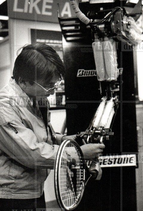
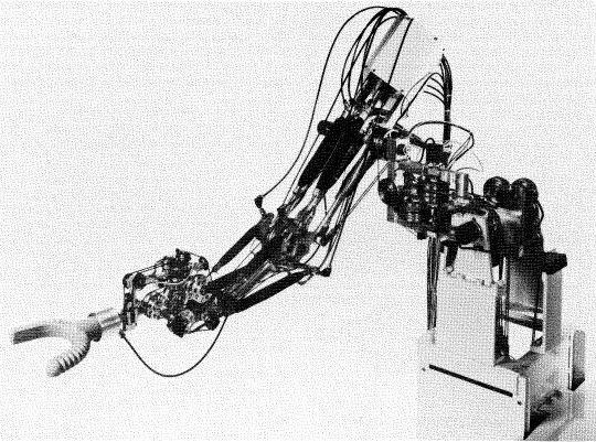
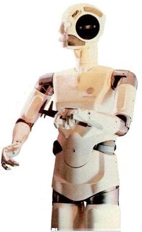
The terminology may not be well-defined, but in any event, Jon Barron, a British engineer, has dubbed his prototype anthropomorphic robot McAndroid the Android. Barron appears with his creation in the photo above.
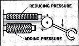
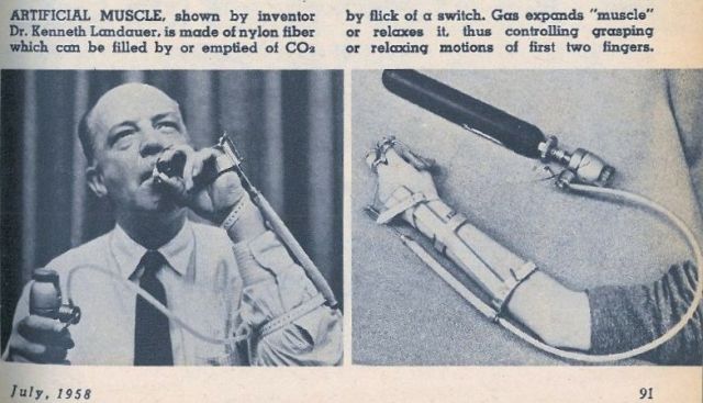
Although he figures that the market for the manlike machine will be the entertainment industry at first, he developed McAndroid as a test-bed for new technology that could appear in robots for home or light industrial use. One possible application is the use of McAndroid's pneumatic valves, which regulate the flow and volume of air into the rolling diaphragm muscles at each of the robot's joints. The simple valve gives fine control of the android's limbs, even though the control system lacks the feedback feature found in industrial robots. Barron's fledgling company, McAndroids Ltd., is also developing software that will program the computer control in a graceful, non-jerky manner, a development that could improve the handling of delicate components on the assembly line.


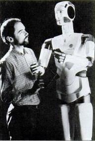
[Photo of Jon Barron with McAndroid]

Popular Mechanics Aug 1985

The day of the android
The movements of robotic limbs often are stiff and halting. McAndroid the Android (right), a fusion of art and engineering, may herald a new era in robotic movement. "Mac" was developed as a sounding board for advanced manipulation technology. He is endowed with pneumatic valves which regulate the flow of air into rolling diaphragm "muscles" at each of Mac's joints.
The valve is simple, yet gives sensitive control of the android's limbs. Limb motions are key to more sophisticated industrial and home-use robots.


 [ partial extract from Robotica – Volume 8 – Issue 02 – 1990 ]

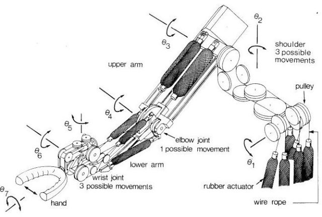
The developers say that anything can be animated by this computer-controlled air-muscle system McAndroids Ltd. (UK) has produced an 'android' robot using air-springs developed by Firestone Ltd. Three air springs were used to power each arm and to give five degrees of freedom.

Also Robotica 1987

p150

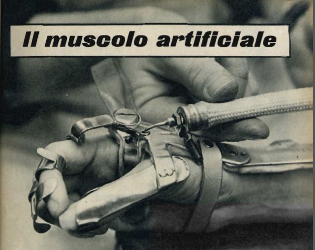
RUBBER MUSCLES FOR ROBOTS
The United Kingdom company McAndroids Ltd. of London are said to be one of the first in Europe to explore the possibilities of making the mechanical man of science fiction a reality.
The company's first android greeted visitors to the 'Robots' exhibition at the Victoria and Albert Museum in 1984 with a lifelike computer controlled body movements. Three air springs are used to power each arm, giving five degrees of freedom. The company say that the air springs are highly engineered rubber bellows made by Firestone, and powered by compressed air which is controlled by a specially designed computer-driven valve system. ENDS

 p150

Their use as robot muscles is a new development which began in 1983, soon after the introduction of Firestone's 1M1A, their newest and smallest air spring. The actuators are powered by compressed air via silicone rubber tubes running from a compressor up the interior of one leg. Fine pressure control is achieved by computer-controlled valves, designed and patented by McAndroids. The valves work on a mechanical feedback follow-up servo system which enables the arm to move smoothly to its required position, and to have a load compensation facility. Computer programs for the androids are stored on floppy discs. New sequences of movements can be either programmed from a computer terminal, or the android can be directed by a human operator using a joy-stick; the computer will remember the movements and times at the various positions and repeat them to order, running the android for extended periods without supervision.

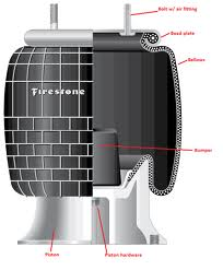
The air springs were highly engineered rubber bellows made by Firestone Ltd.


The Modesto Bee – Mar 10, 1988

 These musicians have tin ears
The Associated Press
LONDON — A flutist with rubber lips, metal fingertips and not much else by way of physique is the latest graduate of the McAndroids laboratory in south London.
Being a robot and brand-new, it doesn't have a name yet, but its first public recitals will be given in September, when it goes on display at Taiwan's new National Museum of Natural Science.
The flutist was born in the same cluttered workshop as Tin Twin, the guest keyboard player who thrilled teen-age fans of the Thompson Twins, a British pop group, on its 1986 world tour.
Like Tin Twin, the flutist is a robotized "musician" developed by McAndroids Ltd., a special effects and 3-D animation team composed of two sculptors, a mechanical engineer and a computer artist.
McAndroids' art and technology creations have been on display since 1984 in museums, traveling exhibitions and on TV shows across Western Europe.
The flutist is going to Taichung in Taiwan along with a collection of musical instruments that visitors will be able to play without touching. Set inside glass cases, the flute, organ, tubular bells, 16-string Chinese zither and drum kit are activated by pressing buttons.
"It's very much a hands-on, discover for yourself exhibit." said sculptor Richard Glassborow. "On one level it's entertainment; on another level it's seriously stimulating."
The push buttons give spontaneous but precise control of the robotics that work the instruments. They can pluck out individual notes or create pulsating effects such as vibrato, tremolo or echo
Musical phrases, such as a bass line, can be instantly recorded and the playback accompanied by improvisation. The instruments also can he commanded to play a simple preprogrammed tune.
"It was a choice to make it simple," said Glassborow. "If you make it very rich, they (the public) just stand and look at it. We wanted to make it very friendly."
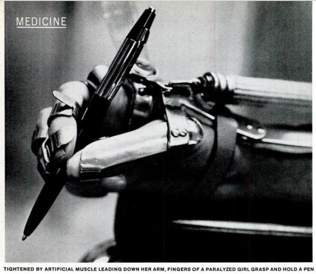
The flute's robotics are the most impressive, employing the head and pneumatically controlled fingers of a humanoid robot, or android. A valve controls the air that is pumped through the delicately positioned rubber mouthpiece into the lip plate.
The instruments took three months to build and were sold to the designers of the museum's soundproof "cacophony section" for nearly $87,000.
They demonstrate an individual's musical inventiveness and allow those without any musical skills to play music, according to Glassborow.
Tin Twin is a more readily recognizable android, with long arms that flit across the keyboard in simulating such smash hits of The Thompson Twins' as "Doctor Doctor" and "Sister of Mercy."
From a distance, the flashing lights in its eyes and mouth give the impression that it is singing along in the chorus.
McAndroids is made up of the 39-year-old Glassborow; Alan Dun, a 37-year-old sculptor; engineer Jon Barron, 34; and Trevor Piper, a 32-year-old artist. The company has found a niche in a fast-growing European market for special effects.
In 1986, its three robotic "French heads," composed of odd-shaped pieces of steel and glass fiber on top of tall poles, turned real heads at a robot sculpture display in the Georges Pompidou Center in Paris.
Vaguely resembling outer-space creatures, they turn to watch passers-by, stop and stare back, or babble among themselves in jolly jingles. A museum in Glasgow, Scotland, is negotiating for display rights.


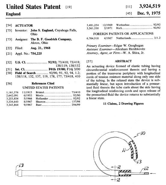
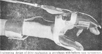
PNEUMATIC SUSPENSION DEVICE R. W. BROWN et al
See full patent here.
Patent number: 2133279
Filing date: Jan 3, 1936
Issue date: Oct 18, 1938


Further information is sought about McAndroid, Tin Twin, and the Flute-playing Robot. Please contact cyberneticzoo.com or post a comment.

1968 – Artificial Muscle Bioprosthesis – (Polish)

Modell einer Bioprothese mit künstlichem Muskel pneumatischer Art. Der Muskel besteht aus einem Gummirohr, in dessen Wände längs der Mantellinie nichtdehnbare Fäden angeordnet wurden. An den Enden sind die Gummikörper mit Endstücken zur Befestigung und Luftzuführung abgeschlossen. Beim Aufblasen des Muskels mit Druckluft verkürzt er sich und erzeugt damit eine Bewegung.

English translation

Model consists of a bioprosthesis with artificial muscle pneumatic type, the muscle of a rubber tube in the walls of which were along the generatrix of inextensible filaments arranged. At the ends of the rubber body with end pieces for fastening and air supply are completed. Shortened upon inflation of the muscle with compressed air thus producing a movement.

Source: Golems Enkel – Stefan Hesse 1988 (1986)

Bioprosthesis Robot Model

Pneumatic Bioprosthesis from Warsaw, Poland, 1968. Image source: Getty images


Further information sought on this arm. Please contact cyberneticzoo.com or leave a comment.


Tags: , , , , , , , ,

1983 – Bridgestone “Rubbertuator” – Takeo Takagi and Yuji Sakaguchi (Japanese)

CAPTION: ROBOTS ON PARADE Keisuke Inada of Bridgestone Corp.of Tokyo adjusts the Soft Arm robot, a multijoint robot that resembles a human arm in its movements, at Cobo Hall. The Society of Manufacturing Engineers expects 25,000 people to attend its AUTOFACT '90, an exposition demonstrating computer-integrated manufacturing. Photo is dated 11/13/90.

Pneumatic actuator for manipulator Takeo Takagi et al
Patent number: 4615260
Filing date: Apr 25, 1984
Issue date: Oct 7, 1986
Japanese pat in 1983

See full patent here.


The Hybrid robot was mainly used for spray painting. Instead of being static, the arm could move sideways on a horizontal plane.

The Servo Rubbertuator Kits came with 2 pneumatic muscles, as in most cases they were to be used as an antagonistic pair i.e. each side alternatively 'pulls' as do the human muscles and joints they simulate.


Pop Sci May 1985

Rubber-armed robot
Working together in Japan, researchers at Bridgestone Corp. and Hitachi Ltd. have developed what may be the most humanoid industrial robot yet. Using novel rubber "muscles" and a rubber "hand," the new robot arm (right) can perform delicate assembly tasks. At its heart are rubber actuators that power each of the arm's seven degrees of freedom of movement.

Caption: Bridgestone's rubber actuators are used in pairs. Robot's hand moves down as bottom actuator is filled with compressed air and top one is emptied.

These actuators, shaped like sausages, behave much like human muscles, shortening and lengthening as compressed air is fed in or bled out. This linear motion, transmitted through arm to bend at its various "joints." The actuator—called the Rubbertuator- is made from a high-molecular-weight rubber tube covered with braided fiber. A flange at each end permits the entry and exit of compressed air. Bridgestone developed the rubber used in the actuator during research into long-life automobile tires. Hitachi built the arm's mechanical components. The prototype arm works under the direction of a 16-bit microprocessor, and it can lift objects weighing as much as 4.4 pounds in its simple horseshoe-shaped rubber "hand."
One of the main advantages of rubber actuators, engineers say, is that they can control not only the movement of a robot's arm but the force of that movement. Thus, rubber-armed robots can be designed to carry out the low-force tasks assigned to them but will stop should they encounter a human worker. Because the robot is pneumatic, it can be supplied by a remote air compressor, permitting installation where space is limited. Hydraulic robots, another common type, require their own bulky power supplies nearby. Bridgestone and Hitachi are now marketing their robot to companies that perform precise assembly operations using fragile components. —Stuart F. Brown

For a more complete article of the Bridgestone-Hitachi Arm see "Rubber muscles take robotics one step further" in Rubber Developments Vol 37 no 4, 1984 pdf here.


"ROBIN" – Vanderbilt University Bridgestone "Rubbertuator"-based Wall Climbing Robot.

ROBIN [ROBotic INspector] was patented September 3, 1996 in the United States (Patent Number: 5,551,525) by Robert T. Pack, Moenes Z. Iskarous, and Kazuhiko Kawamura.

Technical Description
ROBIN is a 4 DOF serial mechanism with fixtures at each end. By fixing one end of the mechanism and moving the other, ROBIN can walk, turn and transition between surfaces. ROBIN uses all off-the-shelf gears, bearings, and fittings so the system can be reproduced easily and inexpensively. ROBIN's motions are powered by Rubbertuators which are rubber pneumatic muscles that have a high strength-to-weight ratio. The pneumatic muscles and vacuum fixtures are controlled by a master-slave network of microcontrollers that continually monitor pressure, valve settings, and joint angles to keep the robot in position and on course. Chain tension of each joint is maintained by a "torque" controller. Initially, each joint's microcontroller is loaded with a table of pressures and corresponding encoder positions. Motion is achieved by applying an additive pressure, or "torque", to a rubbertuator in the desired direction of rotation. Power is provided to the robot by an umbilical cord that carries air lines, DC power, and a serial communication line for interfacing with a host computer that directs ROBIN's actions.
Advantages of ROBIN

  • High Mobility
  • Walks on planar surfaces (horizontal or vertical).
  • Transitions between horizontal and vertical surfaces, as shown in this image.
  • Steps over obstacles and gaps on surfaces.
  • Large Sensor Payload – 8Kg for prototype.
  • Scalable to Task – Design can be enlarged or miniaturized for a specific task.
  • Light Weight – 20Kg for prototype.
  • Versatile Fixtures – Handles many types of surfaces using interchangeable vacuum, magnetic, and grippers.
  • Parallel Multicontroller – Modular, extensible control system that can support fault tolerance and hot-swapping of controllers.
  • Applications of ROBIN
  • Building Inspection – Outer walls, windows, elevator shafts.
  • Aircraft Inspection – Wings, fuselage, cowling, engine mounts.
  • Ship / Tanker Inspection – Outer Hull, inner tank surfaces.
  • Bridge Inspection – Support columns, superstructure, bearings.
  • Behavior Explanation
Patent number: 5551525
Filing date: Aug 19, 1994
Issue date: Sep 3, 1996
See full patent here.

Tags: , , , , , , , , , , ,

1967 – B.F. Goodrich “Rubber Muscle” – John S. England (American)

A Slightly different tack was taken by B. F. Goodrich in a "rubber muscle" project. If a straight piece of rubber hose with specially wound reinforcing cord is pressurized with a liquid or gas it will bend to form an arc; if more pressure is applied, the curvature increases until the hose becomes a ring. Goodrich made a six-finger "hand" from this special hose that had some prehensile properties.


The below patent is most likely the patent related to the Goodrich "Rubber Muscle".

ACTUATOR John S. England et al
Patent number: 3924519
Filing date: Aug 21, 1968
Issue date: 1975
See full patent details here.

Tags: , , , , , , , ,

1957 – “Artificial Muscle” – Joseph Laws McKibben (American)

Although "fluidic actuators" had been around for a long time prior to Joseph Laws McKibben's invention, none had been used previously for prosthetic applications, yet alone robotics. It was McKibben's use that coined the term "Artificial Muscle".

Joe McKibben talks about his invention:

More Help For Polio Victims
To bring motion to his little daughter's polio-paralyzed hands, Dr. Joseph Laws McKibben, an atomic physicist at Los Alamos, N.M., has developed a new mechanical "muscle" which some day may help thousands of other paralyzed fingers to move, to grasp, even to write.
The device, a simple nylon tube, powered by bottled carbon-dioxide gas, was demonstrated for the first time at a conference on human disability. "This is the best thing we've had so far for aiding the crippled," said Dr. Kenneth Landauer of the National Foundation for Infantile Paralysis.
Dr. McKibben, 46, is the physicist who triggered the first atomic-bomb test thirteen years
ago at Alamogordo. In 1952, his daughter Karen, now 13, 'Was stricken with polio and was paralyzed from the neck down. Since then she has lived many months in an iron lung at the Rancho Los Amigos Respiratory Center in Los Angeles, one of the fifteen rehabilitation institutions set up by the polio foundation to treat a variety of patients, including many paralyzed by polio. Last fall, Dr. Vernon Nickell, chief orthopedist at the center, asked Karen's father to make some sort of mechanical gadget that would help the girl to use her useless fingers. "I had been considering a hook for Karen's use," Dr. McKibben said last week. "But Dr. Nickell suggested some kind of mechanical 'muscle' instead."
Vital Valve: After studying hydraulic, electric, and gas  methods of moving paralyzed arm muscles, McKibben found a report from German scientists who had designed an ingenious pneumatic gadget operated by carbon dioxide, which inflated a bellows, thereby compressing the arm muscles and creating a pinching motion of paralyzed fingers. "It was simple enough to sketch a valve for the device," McKibben added. "After all, I'm in the business of making vacuum valves."
At the Rancho Los Amigos center, doctors and technicians teamed up to help McKibben perfect a workable device. As it stands now, the "muscle" is a small, rubber-lined plastic tube which lies along the paralyzed forearm and is fitted by a moving splint to the thumb and first and second fingers. When a lever is touched, gas from a 14-inch cylinder flows into the tube, causing a contracting motion, drawing the paralyzed fingers together When the lever Is touched again, the plastic tube is deflated and the fingers relax.
"The device is a wonderful source of energy. It is lightweight, simple, and safe," said Dr. Nickell.
At Rancho Los Amigos it is being used successfully on a small group of paralyzed patients. 1n New York, officials of the National Foundation for Infantile Paralysis announced that they would launch a crash research program in the hope that McKibben's invention will soon be adapted to move both paralyzed shoulders and elbows. The same theory, said Dr. Landauer, may be applicable to artificial limbs and to arms and legs that are weakened, but not paralyzed, thus offering new variety for the limited lives of cripples. When perfected, the gadget will cost less than $100. — From NEWSWEEK.

[Source: The Buckingham Post – Mar 21, 1958 – Originally from Newsweek (date unknown).]

It's interesting in that whilst the muscle itself was based on another German idea, it was the invention and utilization of the control valve  that made this a workable lightweight, shoulder shrugging-controlled prosthetic arm. Even today (2012), it is the control valves that add to the complexity of usage of McKibben Muscles in robotics, orthotics, and the like.  The "German idea" most likely was the development of pneumatically driven prosthetic hands and arms started in 1948 at the Orthopaedic Hospital in Heidelberg. The "Heidelberg Hand" was invented by Dr O. Häfner (Haefner).

[heidelberg pic here]

The pneumatics utilised was an expanding bellows situated within the claw-hand itself .


Another "bellows" assisted arm that may have inspired or was inspired by McKibben's Arm.


TIGHTENED BY ARTIFICIAL MUSCLE LEADING DOWN HER ARM. FINGERS OF A PARALYZED GIRL GRASP AND MOLD A PEN
ARTIFICIAL MUSCLE
No part of man's body is more distinctively human than his hand—and when it becomes paralyzed, few disabilities are more tragic. For years doctors have been looking for a substitute for hand muscles which would enable victims of paralysis to touch fingers to thumb and pick things up. The device above, developed at the Rancho Los Amigos Rehabilitation Center in Downey, Calif., solves the problem.
The artificial muscle is a sheath of woven nylon fitted over a rubber tube. Compressed gas from a cylinder is let into it by a valve which can be operated by any still usable body part. like an elbow. The gas blows up the tube, making it thicken and shorten.
When gas is released, the muscle slims and length. ens again. The muscle is harnessed to two fingers and a thumb made rigid by braces. When it shortens, they are pulled together. When it lengthens, they move apart. This is all the device does—and all it has to do to enable the user to grasp an object and let it go. The new device, permitting paralytics to eat and even type, took years to perfect. Most of the time was spent developing the braces. The muscle itself was invented four years ago by Joseph L McKibben after his daughter (below) was paralyzed by polio. McKibben is a Los Alamos physicist, famous as the man who pushed the switch to detonate the first A-bomb.

[Source: Life Magazine 14 March 1960]

[Source: La Tecnica Illustrata 1960_07 here]


Although the above article says the arm was invented by Dr Landauer, he was one of several who assisted in perfecting what's now called the "McKibben Artificial Muscle".  The above example does not have the shoulder-control valve as designed and built by McKibben.

[Source: Mechanix Illustrated – July 1958]


More recent comments on the McKibben Muscle:

Spinal Cord Medicine: Principles and Practice.
Lin VW, Cardenas DD, Cutter NC, et al., editors.
New York: Demos Medical Publishing; 2003.

Historic Background

The designs for upper limb orthoses were often originally developed for patients with conditions other than SCI. One of the earliest of these was the flexor-hinge hand splint. Originally designed for the polio patient, this orthosis transmitted the force generated by active wrist extension via a mechanical linkage to paralyzed index and long fingers, enabling finger closure against the thumb (10). The design of this orthosis evolved into what today is known as the wrist-driven, wrist–hand orthosis (WDWHO)—formerly called flexor-hinge splint or tenodesis splint). This orthosis offered prehension capability that had obvious application for the SCI patient. Individuals with C6–7 lesions, with strong wrist extensors and paralyzed finger flexors, could utilize the WDWHO to improve function. The orthosis harnesses wrist extensor power and utilizes the power of wrist extension to flex the fingers at the metacarpophalangeal joints against a stable thumb.

Some patients lacked sufficient wrist extensor strength to utilize the WDWHO. The development of external powered designs led to a system that utilized a CO2-powered “artificial muscle” to provide proportionally controlled prehension. This system was designed in 1957 at Rancho Los Amigos Hospital in collaboration with Dr. Joseph McKibben, a physicist whose daughter contracted polio [RH-2012 and was paralysed since 1952]. Dubbed the “McKibben muscle,” it featured a rubber bladder, which was covered with a woven fabric. This unit was attached to the side of the WHO. When pressurized with CO2, the bladder would expand against the woven fabric and shorten in length. This in turn operated a linkage bar, which propelled the fingers into flexion against the stable thumb. A two-way valve, operated by shoulder shrugging, released the pressure to allow finger extension.

By the mid-1960s, smaller, more-powerful electric motors, brought a shift away from CO2 as a source of external power for upper limb orthoses. Electrical external power was coupled to the WDWHO through the use of cables and battery-powered motors. Again, there were obvious potential benefits to the patient with partial upper limb paralysis.

Encouraged by results of the work with the WDWHO, orthotists and biomedical engineers at Rancho Los Amigos Hospital undertook a much more ambitious project—a battery-powered, multidimensional upper extremity orthosis that would attempt to duplicate all major motions of the arm and hand. Designed using anthropometric measurements, this tongue-switch controlled device offered the opportunity for high-level tetraplegic patients to achieve greater independence in ADLs.

In practice, however, externally powered systems typically proved difficult to maintain. Without ready access to technical support personnel who could repair delicate electronic parts, the orthoses fell into disrepair and were discarded. Patient training was, therefore, crucial to the successful use of the orthoses. The complexity of orthotic design required a well-organized training program by occupational therapists. These two factors often proved a deterrent to continued use by all but the most committed patients.

Designs reverted to more simple mechanical components, which proved easier to operate and maintain. One design adapted prosthetic harnessing systems to the WDWHO. Upper limb prostheses have long been powered by the use of strapping systems that utilize contralateral shoulder protraction to operate a cable that opens the terminal device. This principle was applied to the WDWHO with limited success.

Current designs continue to utilize simple mechanical components, which are more easily maintained.


The Life and Times of Joseph Laws McKibben:

….McMillan travelled throughout the country evaluating cyclotrons that might be used for the project and chose the Harvard cyclotron as the best. Manley selected the University of Illinois' Cockcroft-Walton accelerator and two Van de Graaff accelerators at the University of Wisconsin: the "long tank," a 22-foot-long machine that could produce energies of up to 2.6 million electron-volts, and the "short tank," a 17-foot-long machine built by Joseph McKibben, a graduate physics student at the University of Wisconsin who accompanied both accelerators to Los Alamos.

JOE MCKIBBEN is an 82-year-old (as at 1995) retired Los Alamos physicist who made the final connections to the atomic bomb after it was suspended in its tower. He was the last to leave the Trinity site before the explosion.
McKibben, who still lives in the town of Los Alamos, spent the final night at ground zero to ensure the gadget wasn't tampered with. Mattresses had been laid at the tower base as a precautionary move in case the bomb fell, and at 2 a.m. McKibben lay down to get some sleep. He was awakened by a pre-dawn lightning storm that spattered him with rain.
He closed the switches at the base of the tower, drove 800 yards to a relay station and threw switches there, then came back to the tower. Because of the storm the test was pushed back an hour, to 5:30 a.m. Communication was difficult because scientists were using the same radio frequency as a nearby Voice of America station. Finally, he made his final connections and drove to his bunker about two miles away. Photo floodlights were turned on inside to allow cameras to record the final countdown.
Then the bomb went off.
"I had a photo flood on, but suddenly realized there was a lot more light coming in the back door," he recalled. "It was very brilliant outside." He threw one more switch to trigger instruments measuring the blast, then rushed outside 13 seconds after the bomb ignited. "I ran out and took a look at it. It was a big ball of fire, brilliantly colored and highly turbulent. The color was somewhere between red and purple." 
What was he thinking? "I felt we had been successful in our project. I knew the war would soon be over."
Four hours after the explosion, the cruiser Indianapolis steamed out of San Francisco Bay bearing a bomb nicknamed Little Boy. It was headed for the bomber base on Tinian Island in the South Pacific, where it would be loaded on a Boeing B-29 and dropped on Hiroshima, Japan, on Aug. 6. Little Boy was not quite as powerful as Fat Man; it exploded with a force of about 16,000 tons of TNT.
After its delivery, the Indianapolis was torpedoed by a Japanese submarine and its crew was spilled into the water. More than 500 of them drowned or were devoured by sharks.
Pieces of a copy of Trinity's Fat Man, again fueled with Hanford plutonium, were delivered by air to Tinian, assembled and dropped on Nagasaki, three days after Hiroshima. It exploded with the power of 22,000 tons of TNT.
Because of the chaos and obliteration following the bombings and uncertainty about attributing cancer deaths to radiation, estimates of deaths from the two bombs range from 115,000 to 340,000. If the latter is correct — and it is closer to the historical consensus — the two "gadgets" killed more Japanese than all the Americans killed in all the battles of World War II.
They also ended a war that had, with conventional weapons, already claimed at least 40 million people. In just one horrific example, the Japanese army is estimated to have massacred as many as 200,000 Chinese civilians in Shanghai in 1937.